NanoVNA 2Plus4 Quick Teardown
Posted 2021-11-07
Backstory
When I decided on my senior design project for my bachelors two months ago, out of the choices given I chose one which its end goal is to transmit on and characterize the HF band (3-30Mhz). This project I felt was the most appropriate for me, as I do have a slight interest in RF. I also have an amateur license (KC1GCZ), which will make transmission easy on the amateur bands (compared to getting an ISM transceiver). That project, coupled with my increased interest in RF, warranted me to look for a VNA.
Vector Network Analyzer
A VNA is a device, simply put, that transmits a pure signal (sine wave) on one port S1 and measures the reflection on that port and/or the received signal on the other port S2 depending on the mode used, and it does this with a given frequency steps and range. This allows for a lot of information to be gathered and analyzed about the device under test.
For example, if only reflection is measured and the DUT is an antenna, the VNA will be able to measure the SWR of that antenna (a measure of how well the impedance of the antenna is to the impedance of the VNA, which is usually 50Ω), which is useful in tuning the antenna. If a filter is hooked up to a VNA, it can measure the reflection of the filter at its input but more importantly its frequency response by measuring S2’s input.
For more information into VNA’s, check out this article by electronicsnotes which goes into it in more detail.
Unfortunately, most commercial VNAs cost at least 5k$, which is not a sum of money I’m willing to spend on it myself. Lucky, edy555 designed a low-cost VNA under the name NanoVNA which ends up begin around 50$. There are some caveats with this design, mainly above 300Mhz it uses harmonics of the signal generator to “create” the higher frequency signals, which will never be as accurate as generating it without harmonics. This model VNA have been cloned to death, as a quick Amazon search will reveal lots of them. HCXQS re-designed from scratch a slightly more expensive but better performing VNA (that doesn’t use harmonics to generate higher frequency signals) under the name NanoVNA V2. Their recent and currently supported version, the 2Plus4, is 200$ on Tindie and is the one I decided to purchase.
NanoVNA 2Plus4 Quick Teardown
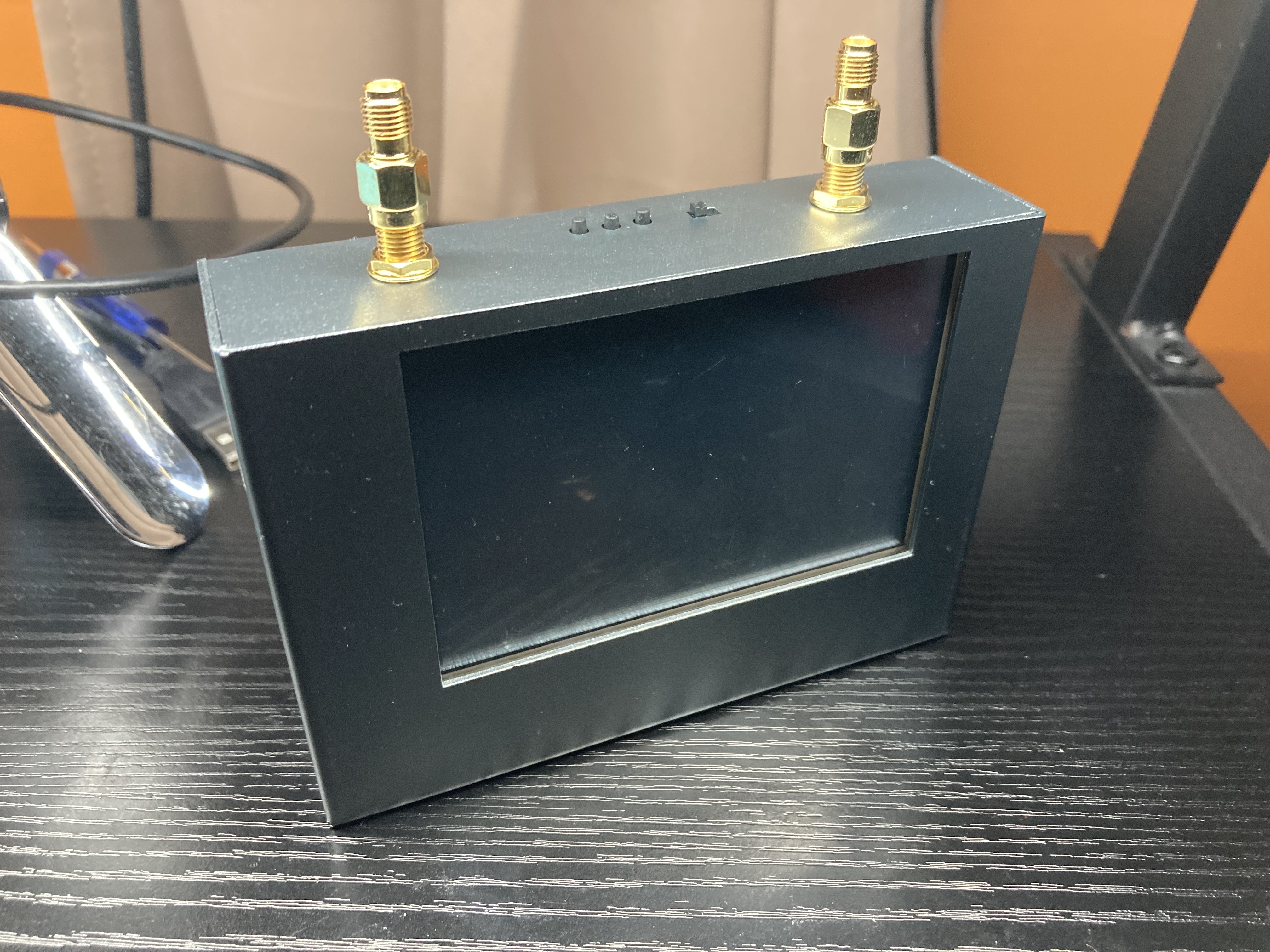
The NanoVNA 2Plus4 comes in a nice metallic enclosure instead of the other NanoVNAs, which should help against some EMI.
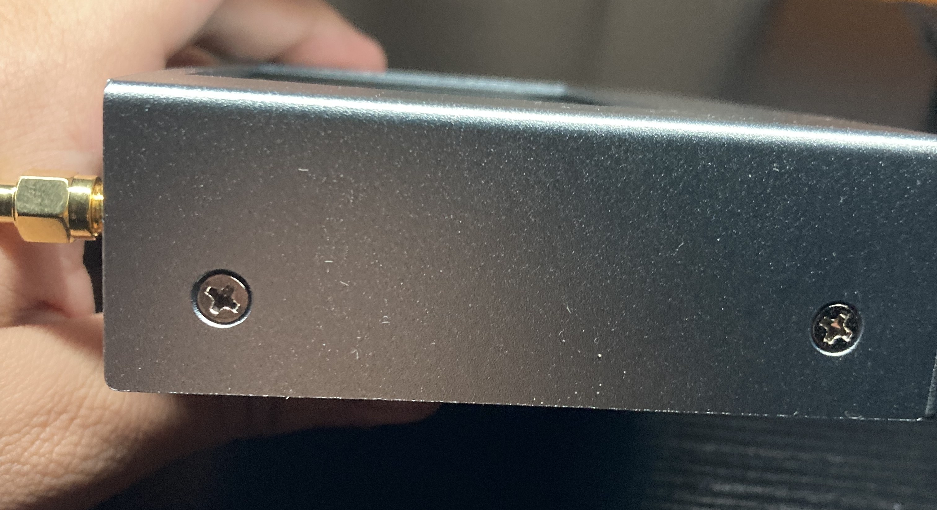
To take it apart, simply remove the 4 screws, two on each side, which are Philips.
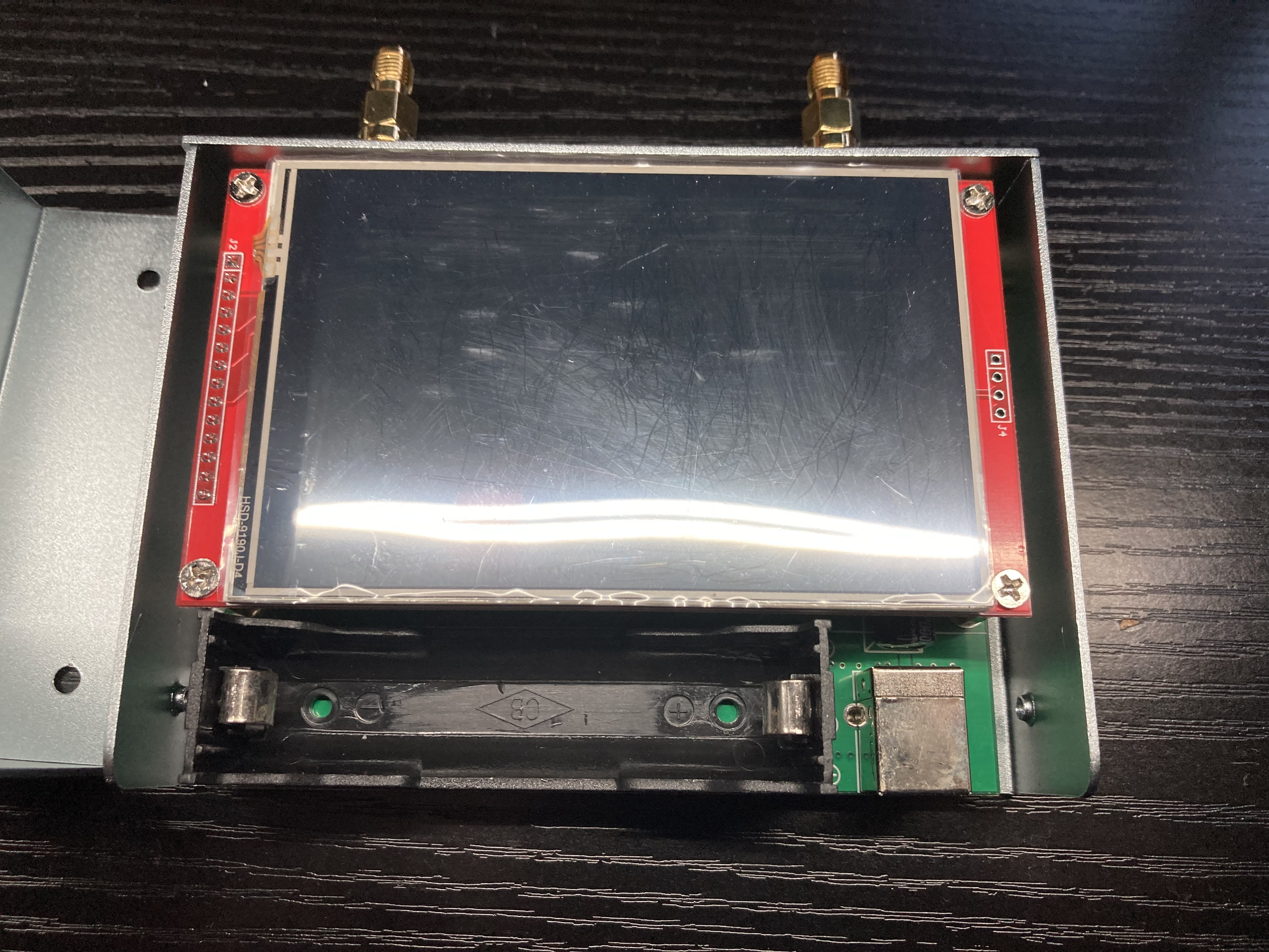
Inside, we can see a battery slot (looks like an generic 18650 cell), the circuit board, and an LCD module with a screen protector still in it.
Something to note is the screw holes are tapped into the metal, which is better than being tapped into plastic for it’s longevity.
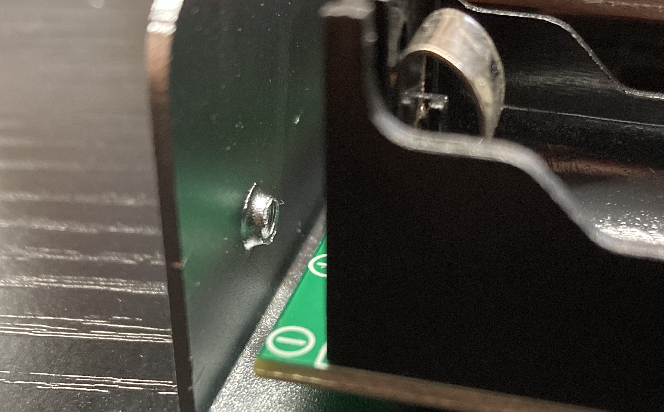
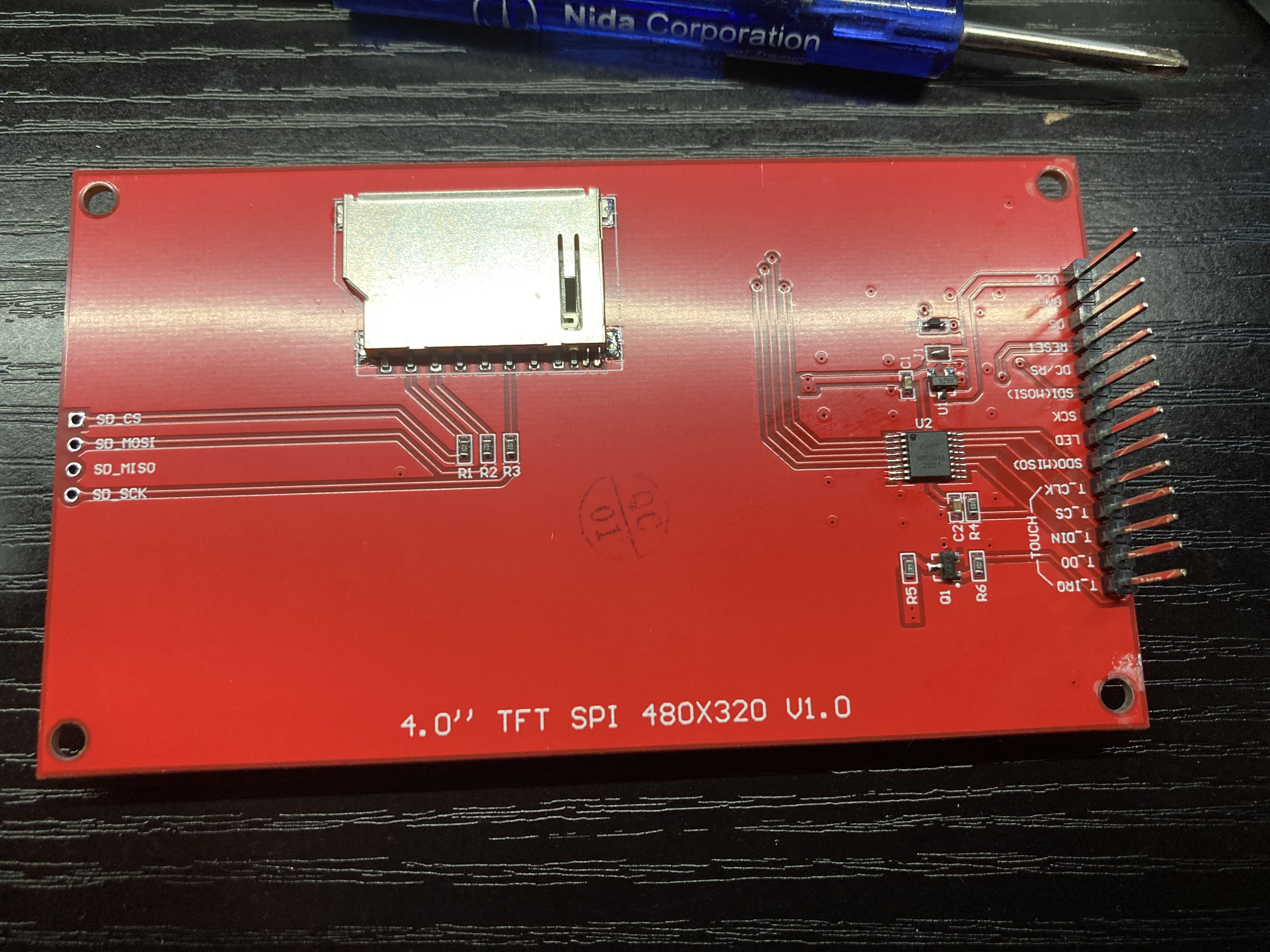
To take apart the LCD module, the 4 screws holding it must be taken out. Those screws are the same as the ones holding the case on the side, which I like. The LCD looks like a generic LCD module which is nice for potentially replacing it. One thing to note about this module is the length of the pin headers.
Taking a look inside this device, there looks there are 4 metal cans soldered on the board: two on the top and the other two on the other side of the circuit board.
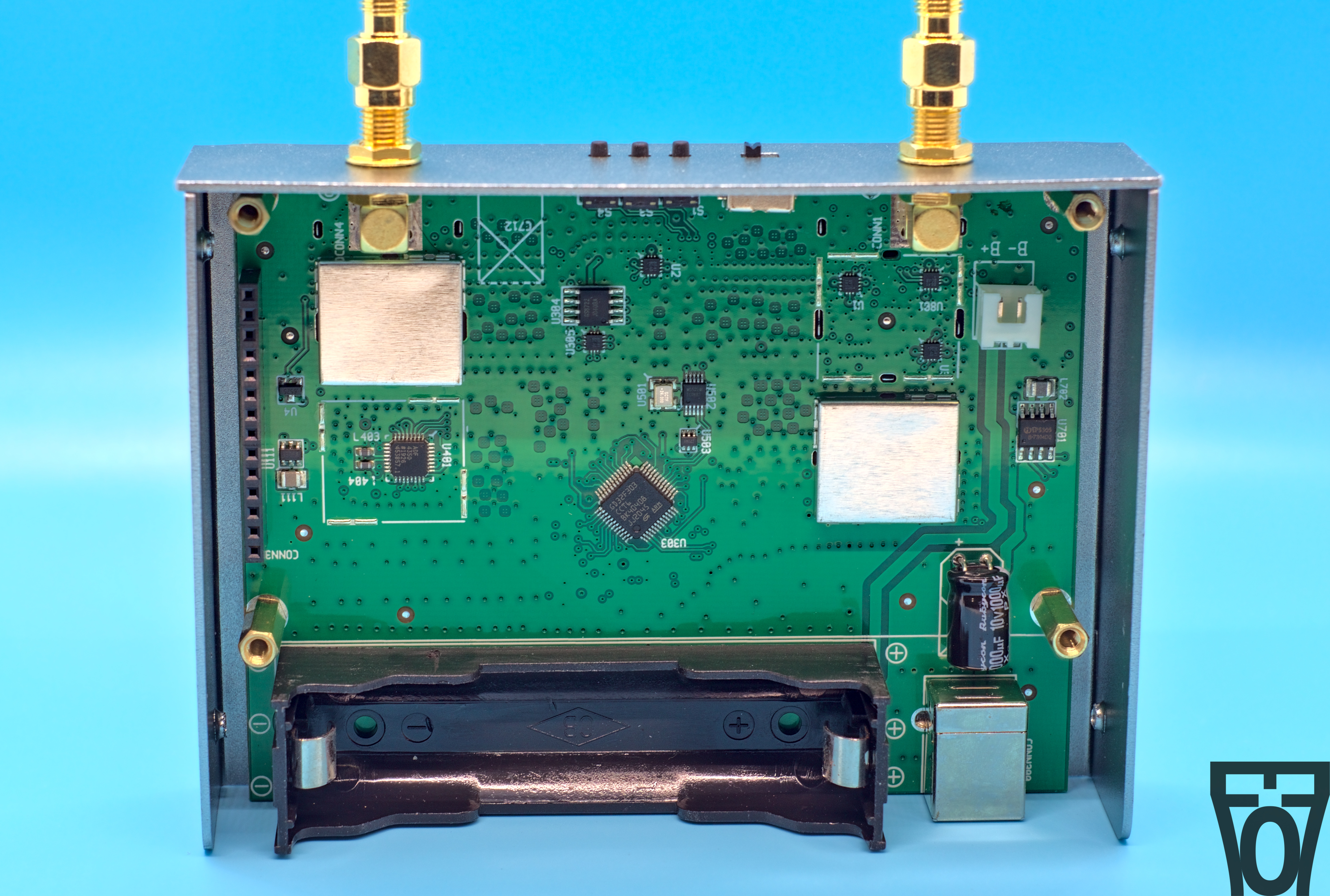
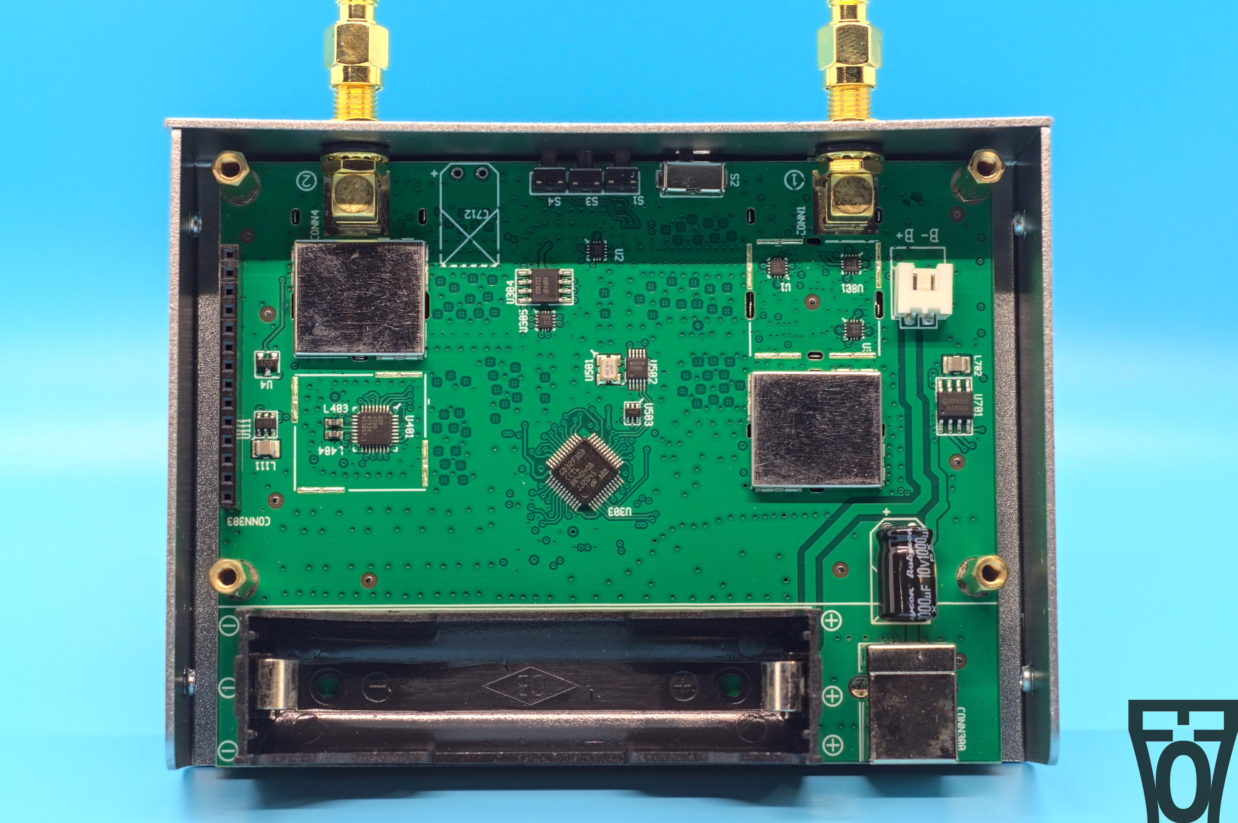
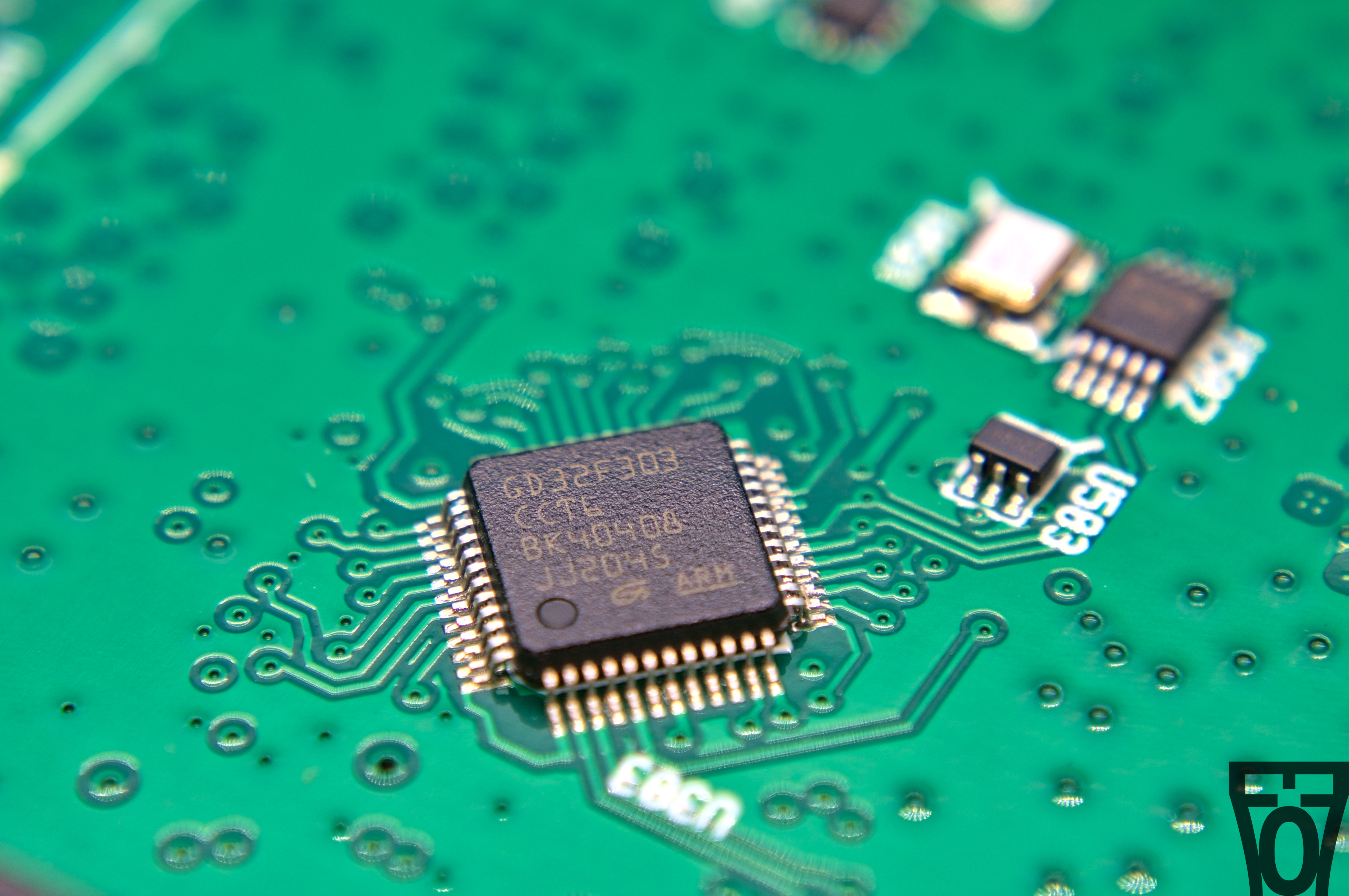
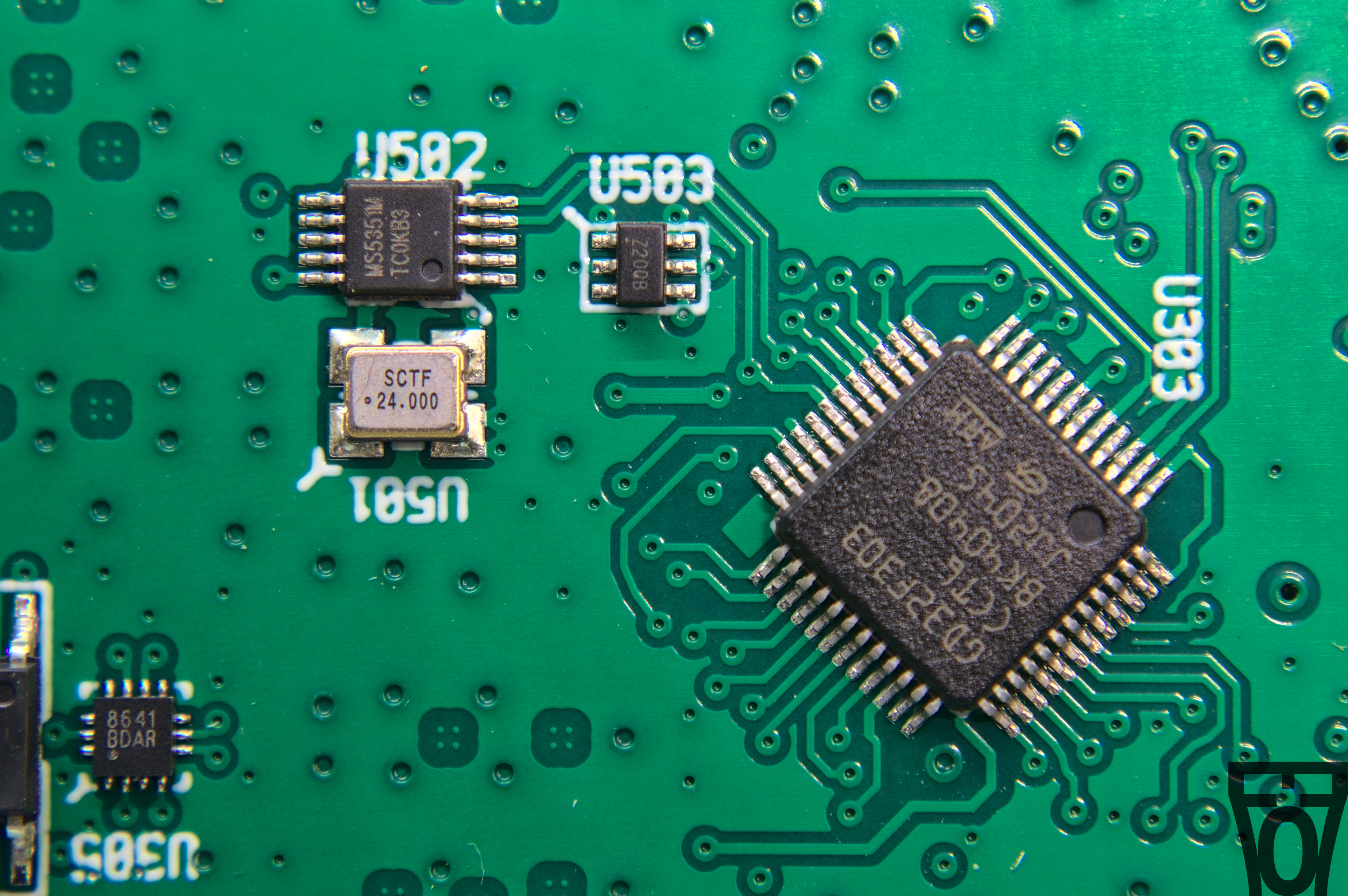
It looks like the main microprocessor is a clone STM32F303 MCU. You know what, after the shitshow which has been STM32 stocks, I don’t blame HCXQS at all. Next to it is a MS5351M clock generator.
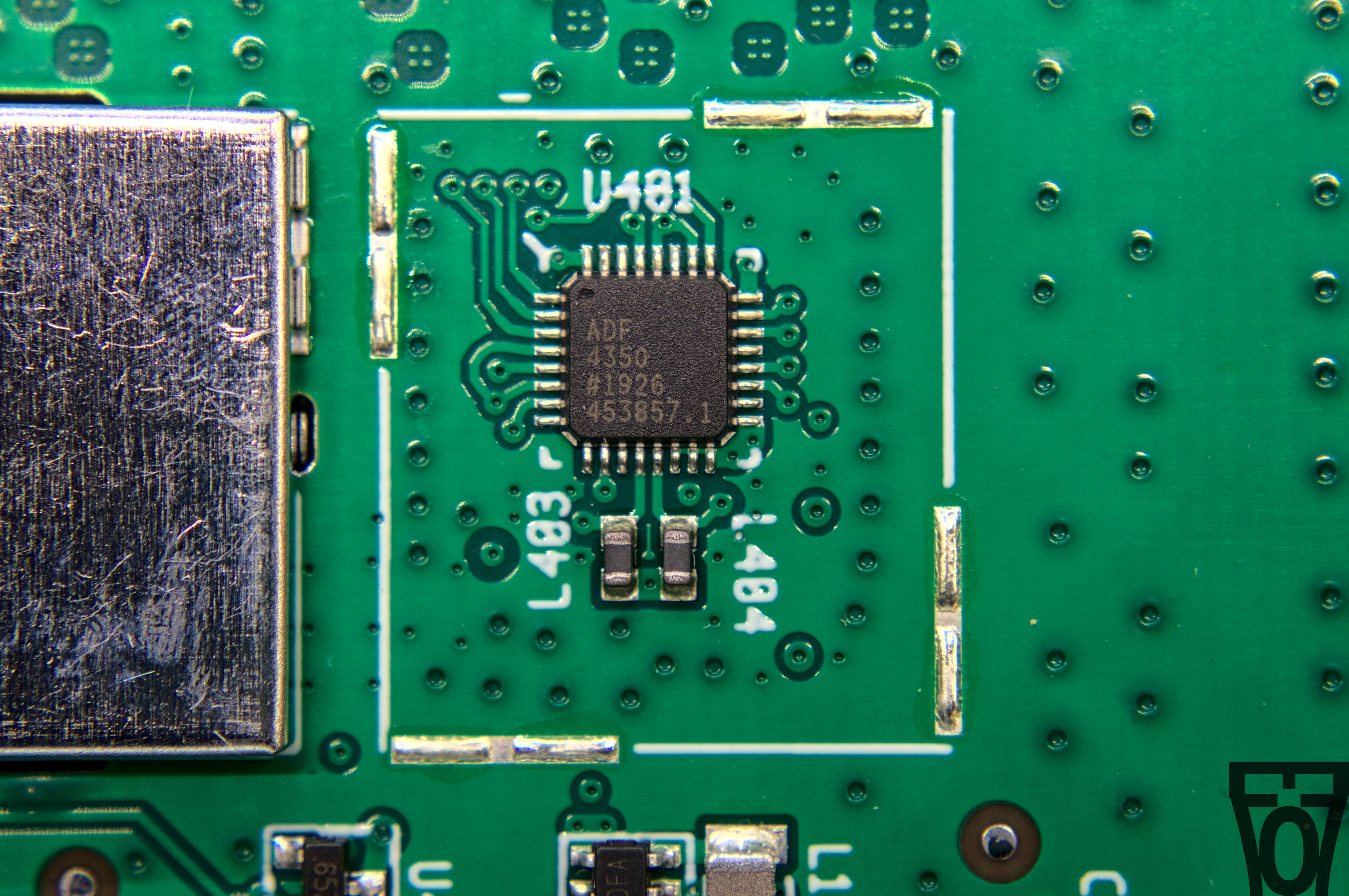
The other interesting active chip is a ADF4350 VCO.
Unfortunately this is where the teardown ends, as I don’t feel like taking apart the other side of the board and taking apart the soldered metal cans.