RP Pico and USB Audio
Posted 2025-02-09
Preface: This page loads MaxJax with the following JS code.
<script id="MathJax-script" async src="https://cdn.jsdelivr.net/npm/mathjax@3/es5/tex-mml-chtml.js"></script>
In this post, I will be writing about and demonstrating a USB audio player, using the RP2040 chip alone with one gpio pin, and the help of an amplifier (LM386) to play the audio on a speaker.
This project originally started from just wanting a USB audio speaker on the RP2040, for an audio spectrograph project I ordered PCBs for.
The code for this mini project can be found over in it’s Github repository, and I will be partially referencing that code in this post.
Keep in mind that I am just learning about this (more on the USB audio interface end), so take this post as more of a log of my journey if anything.
USB
Audio
The first step in this project was to get USB audio working.
I will be honest, I am NOT a usb expert at all, especially not for audio. Thankfully, the library I was planning on using, tinyUSB, has several audio examples, including a mono speaker, which is exactly what I wanted. So I was able to mash example code together to get something working.
I first started by mushing examples together to build a USB-CDC (i.e serial port) example, then added audio on top of that.
I used the pre-defined TUD_AUDIO_SPEAKER_MONO_FB_DESCRIPTOR descriptor to setup the audio interface. I did try initially creating my own (the giant commented out block in usb_decriptor.h), before I realized tinyUSB already has one defined.
I will not be going over USB’s audio interface class, as I am both not too familiar, and also would take a while to write up. I may write something in the future, as I dig through more example code and the USB audio specification.
The audio data from the USB interface will be in pulse-code modulation, i.e the audio data will contain the signal’s amplitudes over time sampled at the audio sampling rate, set at 48Khz for this example.
PI Reset
If you every uploaded a project unto the Pico, and you were using the pico_enable_stdio_usb option in your CMAKE file, you may notice you did not have to press any boot button. That is because that option, on top of creating a USB-CDC interface to act as a “serial port”, also creates a custom interface specifically for the PI to reset on command.
If you want to include this in your own custom USB project, you need to
- Add
pico_stdio_usbto thetarget_link_librariesoptions in your CMAKE file - Add the following line to your CMAKE, which add C defines to allow the USB reset code to not be removed by the pre-processor
add_definitions( -DPICO_STDIO_USB_ENABLE_RESET_VIA_VENDOR_INTERFACE -DPICO_STDIO_USB_RESET_INTERFACE_SUPPORT_RESET_TO_BOOTSEL -DPICO_STDIO_USB_RESET_BOOTSEL_INTERFACE_DISABLE_MASK=0 ) - Add the following copied descriptor define in your
usb_descriptors.hfile#define TUD_RPI_RESET_DESCRIPTOR(_itfnum, _stridx) \ /* Interface */\ 9, TUSB_DESC_INTERFACE, _itfnum, 0, 0, TUSB_CLASS_VENDOR_SPECIFIC, RESET_INTERFACE_SUBCLASS, RESET_INTERFACE_PROTOCOL, _stridx, - Finally, add the
TUD_RPI_RESET_DESCRIPTORdescriptor to yourusbd_desc_cfgvariable.
While it’s a bit of a “hack”, it seems to work just fine.
Audio Interrupt
As we receive audio data from a pc, we would want to update the audio pwm at the same sample rate as set in the audio interface (so 48kHz for this example). As issue the propped up is the default PI clock, 125Mhz, doesn’t divide evenly into 48Khz (\(\frac{125Mhz}{48kHz}=2604.1\overline{6}\)).
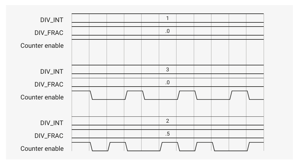
Now you might think this isn’t an issue as the PWM peripheral on the RP2040 has a “fractional” clock divider. But similar to how most fractional dividers work (I remembered something similar on a PIC32), it does this by having a variable clock rate, generating an average of your desired fractional clock. From Figure 111 in section 4.5.2.4 in the RP2040 datasheet, you can see for a 0.5 fractional divider, the output clock changes widths from 1 to 2 input clock periods.
For some applications this varying clock is ok, but for our case is absolutely is not. The solution I used was to simply change the Pico’s clock frequency from 125Mhz to 126Mhz, which nicely divides into 46Khz. The clock can be changed with the following cmake definitions:
add_definitions(
    -DSYS_CLK_HZ=126000000
    -DPLL_SYS_VCO_FREQ_HZ=1512000000
    -DPLL_SYS_POSTDIV1=6
    -DPLL_SYS_POSTDIV2=2
)
The first define is for functions that need to know the system clock, like delay functions. The second define sets the VCO inside of the PLL module to generate a 1.512Ghz signal, then it gets divided by the second and third defines (1.512Ghz / 6 / 2 = 126Mhz)
I then created a PWM timer that overflows and interrupts every 48Khz.
pwm_clear_irq(PWM_AUDIO_INT_SLICE);
pwm_set_irq_enabled(PWM_AUDIO_INT_SLICE, true);
pwm_set_wrap(PWM_AUDIO_INT_SLICE, 2625-1);
pwm_set_clkdiv_int_frac4(PWM_AUDIO_INT_SLICE, 1, 0);
pwm_set_enabled(PWM_AUDIO_INT_SLICE, true);
...
irq_set_exclusive_handler(PWM_IRQ_WRAP, audioPwmWrap);
Audio Playback
So we are able to, in theory, get USB audio packets from a USB interface. Next step was to actually play this audio.
We could purchase an external DAC and use that to play the audio. Because I didn’t have one, I instead decided to play the audio over a single GPIO pin with PWM. I also did this in the past (see this old project), so I was familiar with the concept and knew this would work.
1-Pin PWM DAC
Signal PWM Modulation
If we take a PWM signal, and encode our desired signal’s amplitude as the duty cycle, then the resulting PWM signal will be a combination of the carrier (a square wave) and our signal in the frequency domain. This is referred to a Pulse Density Modulation (PDM) signal.
This concept to me was inspired by a Class-D Amplifier
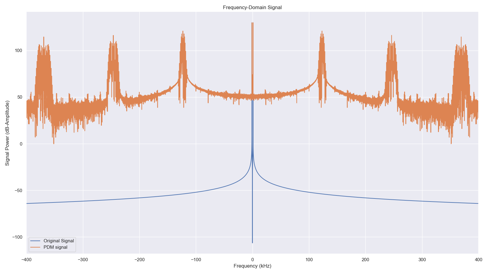
If we have a high enough carrier (say 10x our audio bandwidth), and filter it out, we are able to extract baseband audio from a varying PWM signal.
Below is a Python simulation of that, with a 1Khz sine wave. The PWM frequency and low-pass filter are chosen based off what I built up, details in later sections:
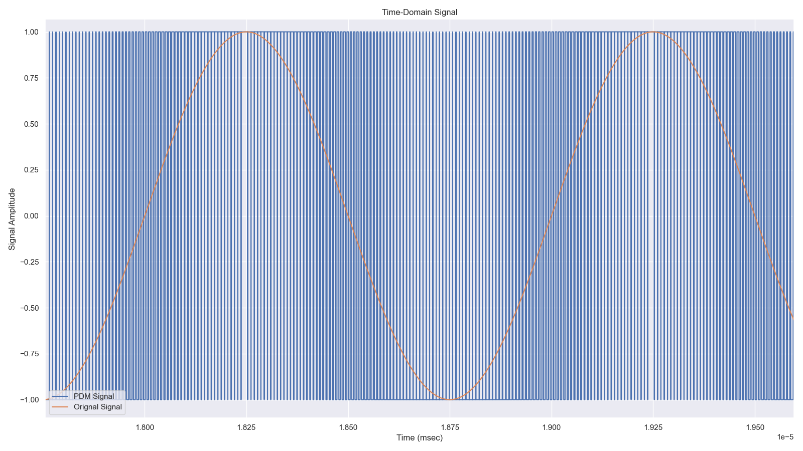
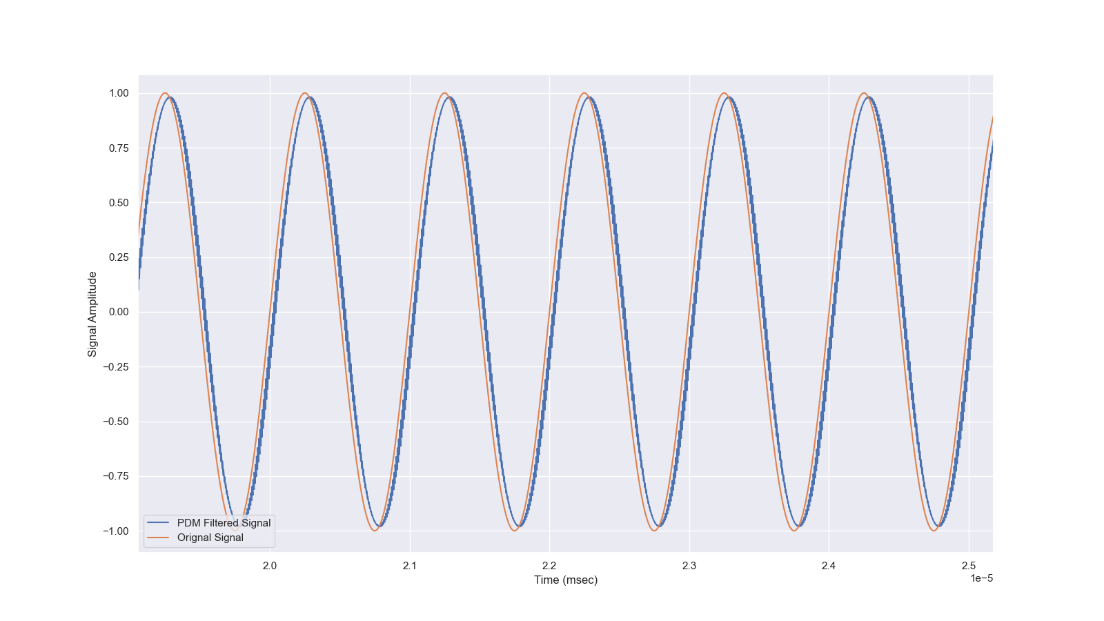
So on our microcontroller, all we would need to do is update the PWM duty cycle with the amplitude, the filter the output.
Timer Frequency Limitation
On the RP2040, there are PWM modules. They are essentially timers that count up and reset at a certain value, and can toggle an output pin when the timer crosses a threshold value and on timer reset.
This sort of creates an issue, where the PWM duty cycle resolution, thus effectively our audio resolution, is dependent on how much the PWM module counts up to. The RP2040 can count up to 0xFFFF (16-bit), so in theory we are able to do 16-bit audio. The issue is with a system clock of 126Mhz, that results in the PWM having a frequency of 1.92Khz. This is well within the desired audio frequency, so clearly this will not work. We can change the timer reset value (thus it’s frequency). I did not want to do 8-bit audio, figured it was a bit lame. So I settled on a 12-bit count value, resulting in a pwm frequency of ~123.05kHz. This isn’t quite the 10x that we wanted at minimum, but it should be enough for most basic playbacks.
Amplifier and Filter
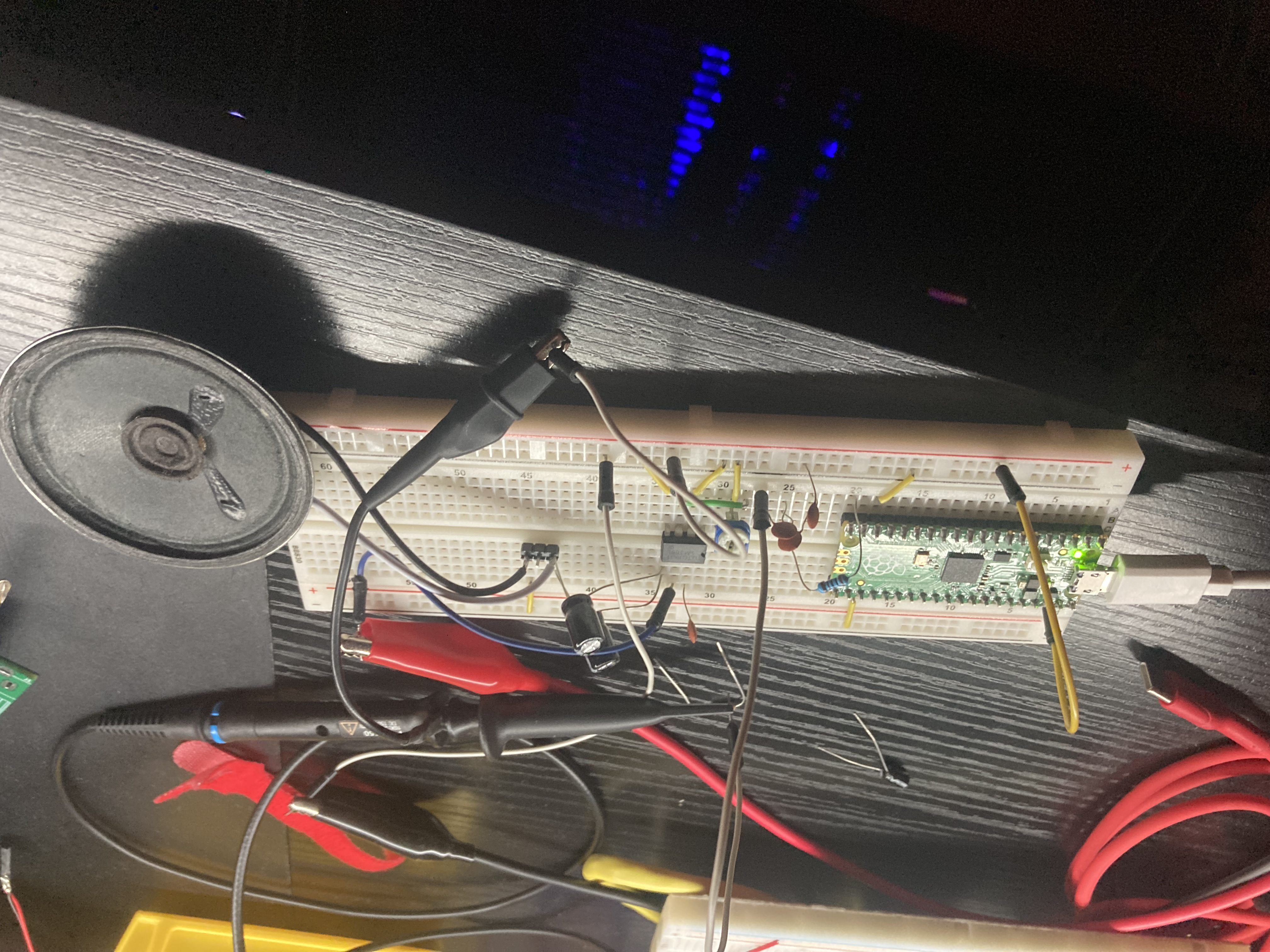
As you might guess, the Pico’s GPIO isn’t enough to drive a speaker on it’s own. For that, I used the LM386 amplifier, mainly because I had it, and it was simple to use, and is specifically designed to directly drive a speaker.
Of course I have to filter the PWM signal, so I used a series 1kΩ resistor with a parallel 0.33nF capacitor (measured), forming a RC filter with a -6dB corner frequency of 4.82Khz. Yeah it does’t cover the full audio range, but even with the low cutoff some of the PWM signal still reaches the output, see the scope image below. A simulation also somewhat confirms this, see the above simulation image For now I was happy enough with this limitation

I though that we would need to bias the signal away from ground, as the amplifier’s negative supply is ground, and I though the LM386 would clip the signal below ground. Turns out, according to this blog post, that the LM386 is intentionally designed to accept a negative signal below ground, up to -0.4v, so that is cool.
End
At the end, we have a working USB audio interface, with a half-working amplifier able to play music. Pretty cool from a $4 microcontroller
Post Extra: Crap Breadboards
Initially before I was typing this blog post, I prototyped it in a crappy Chinesium™ breadboard I had laying around. When using the ceramic capacitors I had with thin leads, I can get them to disconnect by barely moving the capacitors. I could tell the contact was loose on the capacitor pin.
While re-verifying my circuit for this post, I decided to switch to a genuine BusBoard breadboard, and the difference pays for itself. Makes me wish I switched to it earlier.
TL;DR, if your breadboard is getting intermediate contact and you fell it’s not a good prototype device, give BusBoard a try. They are pricy comparatively speaking, but pay off themselves in the good contacts they make. See this comprehensive video for more info on good breadboards