Connect 4 Soldering Kit Update
Posted 2020-04-19
A while ago, I’ve designed and published a connect-4 PCB: Link to V1 design
I’ve also secretly made a second revision of that board!
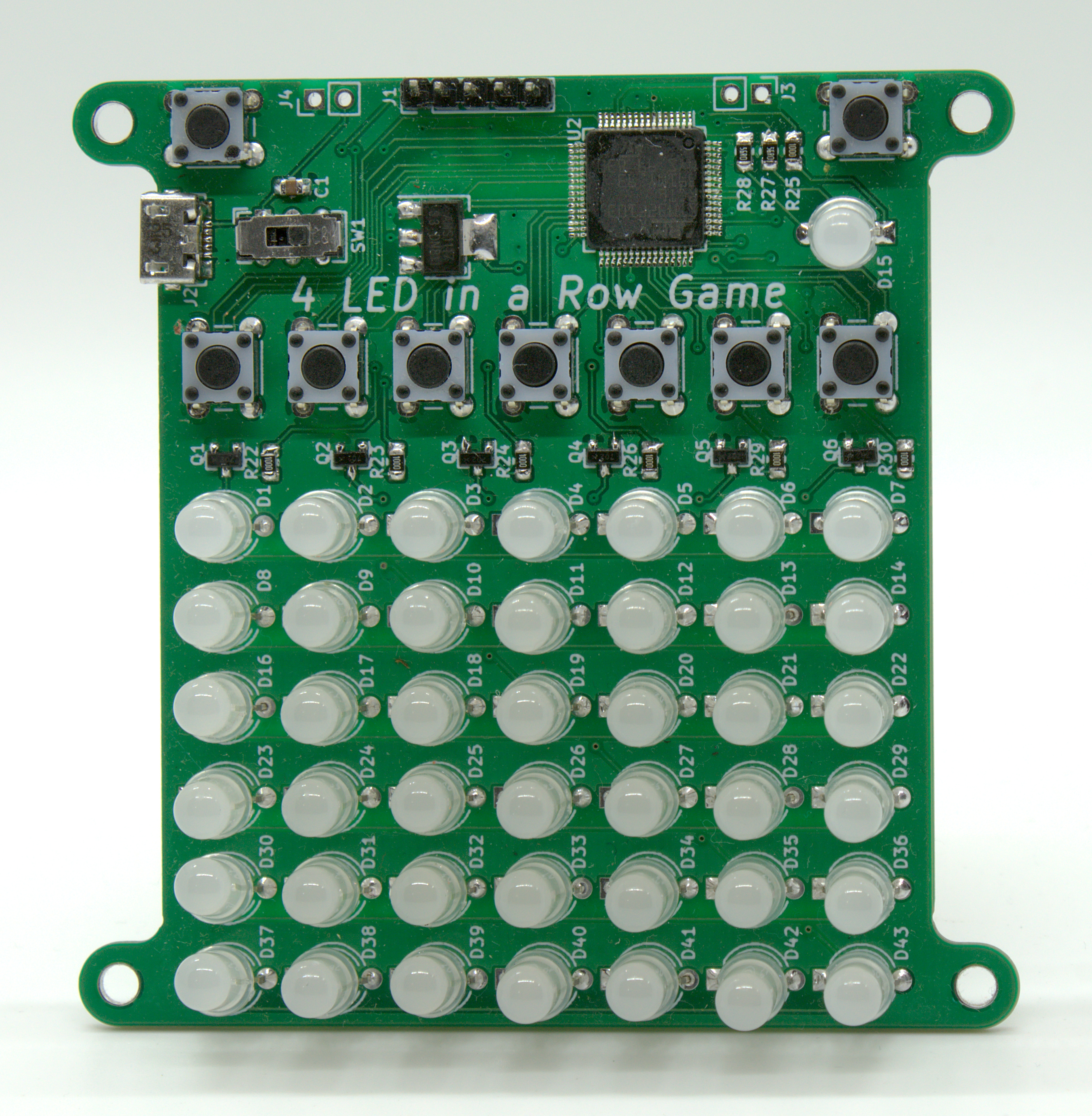
The reason why I did not publish that board is because I was too lazy to, but also because I wasn’t satisfied with it. Mainly I wasn’t satisfied with the microcontroller used. You see originally I ordered the microcontroller thru Aliexpress. There, it was only 2$, the same price as an ATmega328P. But after I redesigned it so that I can potentially sell it/publish it as a soldering kit, I then realized that the microcontroller actually costs ~6$ on official distributors like Digikey. Yikes! For what I was using the MCU for, it definitely was not worth the 6$. On top of that reason, I also wanted to make it beginner friendly, and a 100-pin TQFP package is not too friendly for beginners (It was a pain in my a** to solder it on, even tought I am semi-experienced in soldering SMD parts).
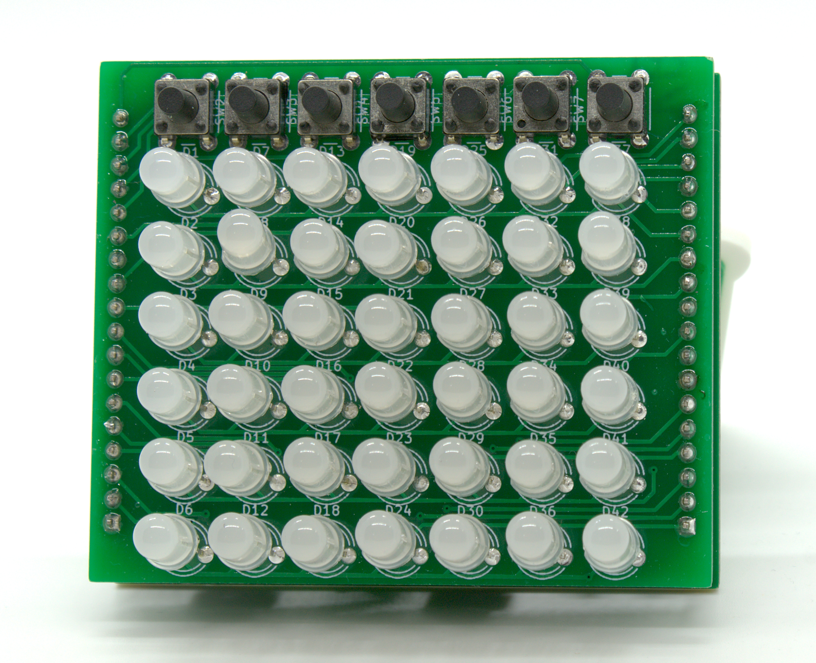
So, I’ve started to redesign the board from scratch, with an easy soldering kit design in mind. First thing I had to do is to remove all SMD packages, as usually beginner hobbyists aren’t comfortable with doing SMD soldering. I also replaced the microcontroller with an ATmega328P, as a beginner usually starts off with an Arduino (which is powered by said chip). As the chips were naturally going to get bigger as I moved to DIP packages, I noticed that the board would look a bit funky if I kept it as a single PCB (either it’s going to be very long with the LEDs and buttons at the bottom, or there was going to be a large rectangular PCB area on top of the game area). Due to that, and because I wanted it to look nice, I’ve decided to make this a 2 PCB design, one for the LEDs and buttons, the other for the driving circuitry. Here’s how that turned out:
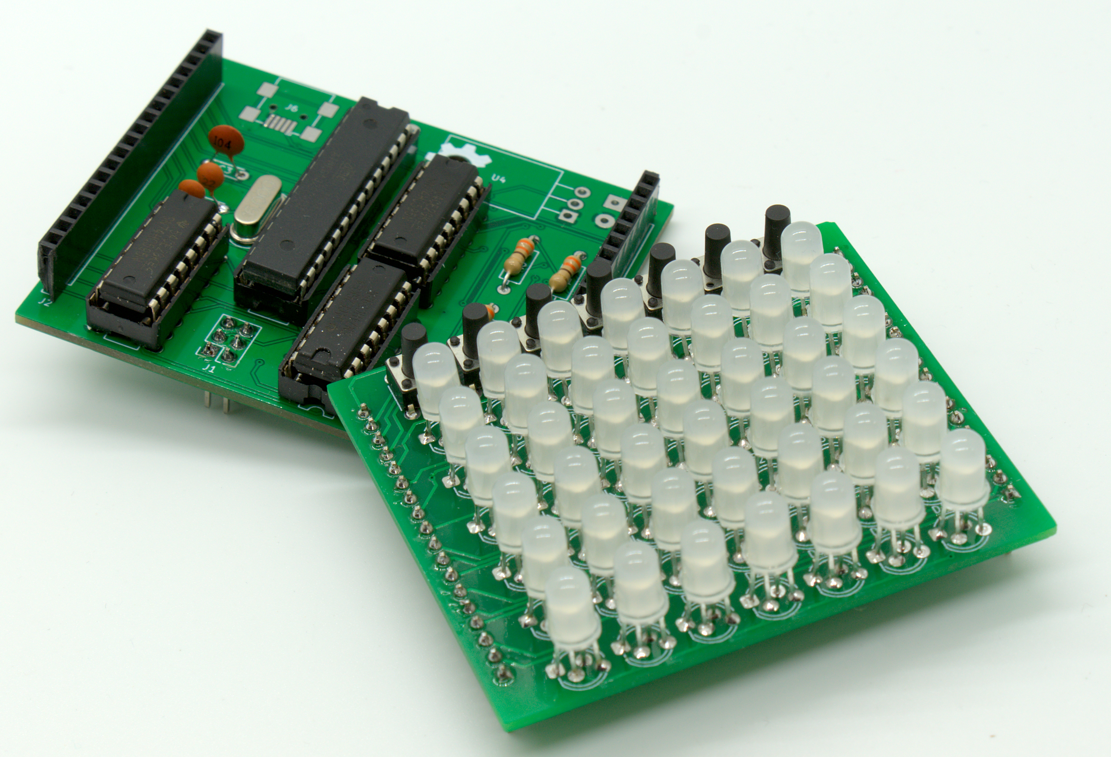 Not too bad! Now all I had to do was drive the thing. I didn’t want to have an LED for each color of the RGBs, as that would result in ~21 individual resistors that have to be soldered. Instead, I will be driving a single color at a time, and current limiting thru the cathodes of the LEDs. This means in theory that, per row update, the red, green, then blue color of that row’s LEDs would need to updated one color at a time. But also due to board size restriction, I didn’t have space to add transistors to drain a row’s LED’s cathodes. Instead, I am relaying on the Atmega to pull them to GND (As the ATmega could both sink and source current). The datasheet of the ATmega specifies that it can handle ~20mA of sink/source current. So, if each LED is drawing ~10mA max, I can comfortably turn on 2 LEDs at a time (one color at a time of course), which is what I ended up doing thru software.
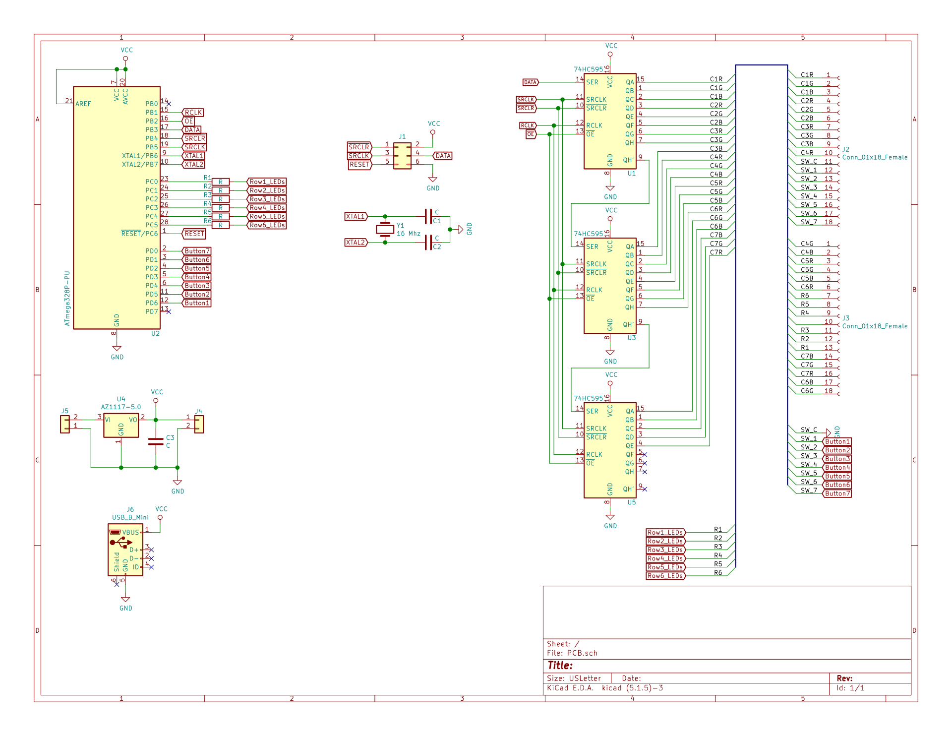
Schematic of redesigned PCB:
 I am still not ready yet to publish it yet. I have made a revision to the design’s driver board, in which I extruded the top of the PCB. The main reason is to add a general button (to, for example, reset the game) and a general indicator LED (to, for example, let whose turn was it). This change will also allow me to add a USB-B connector (current the driver board has a mini-usb instead, which has some partial SMD work). This expansion also allows me to add transistors to drive each row instead of sinking the current thru the ATmega. While I still could only have a single color at a time, now I can turn on an entire row’s R/G/B LEDs at a time, instead of only 2 at a time. This should allow the LEDs to be brighter as well as potentially reducing the frequency the MCU will need to be interrupted. Here is a 3D preview of that new revision:
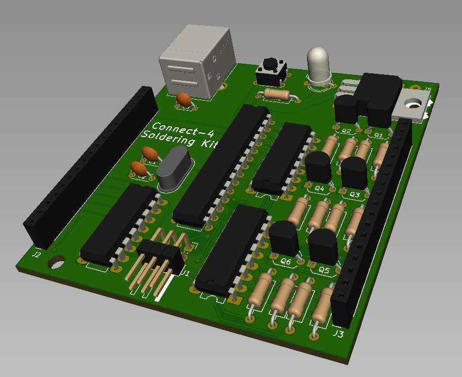 Hopefully, I will order it soon and make a future update on that.