Arduino and Composite Video, part 1: Composite and DAC
Preface: This page loads MaxJax with the following code.
<script src="https://polyfill.io/v3/polyfill.min.js?features=es6"></script>
<script id="MathJax-script" async src="https://cdn.jsdelivr.net/npm/mathjax@3/es5/tex-mml-chtml.js"></script>
Hey I am back some 1.5 year since my last blog post!
As you figured by now I tend to not post much, primarily due to my laziness to write. I probably should get more in the habit of it.
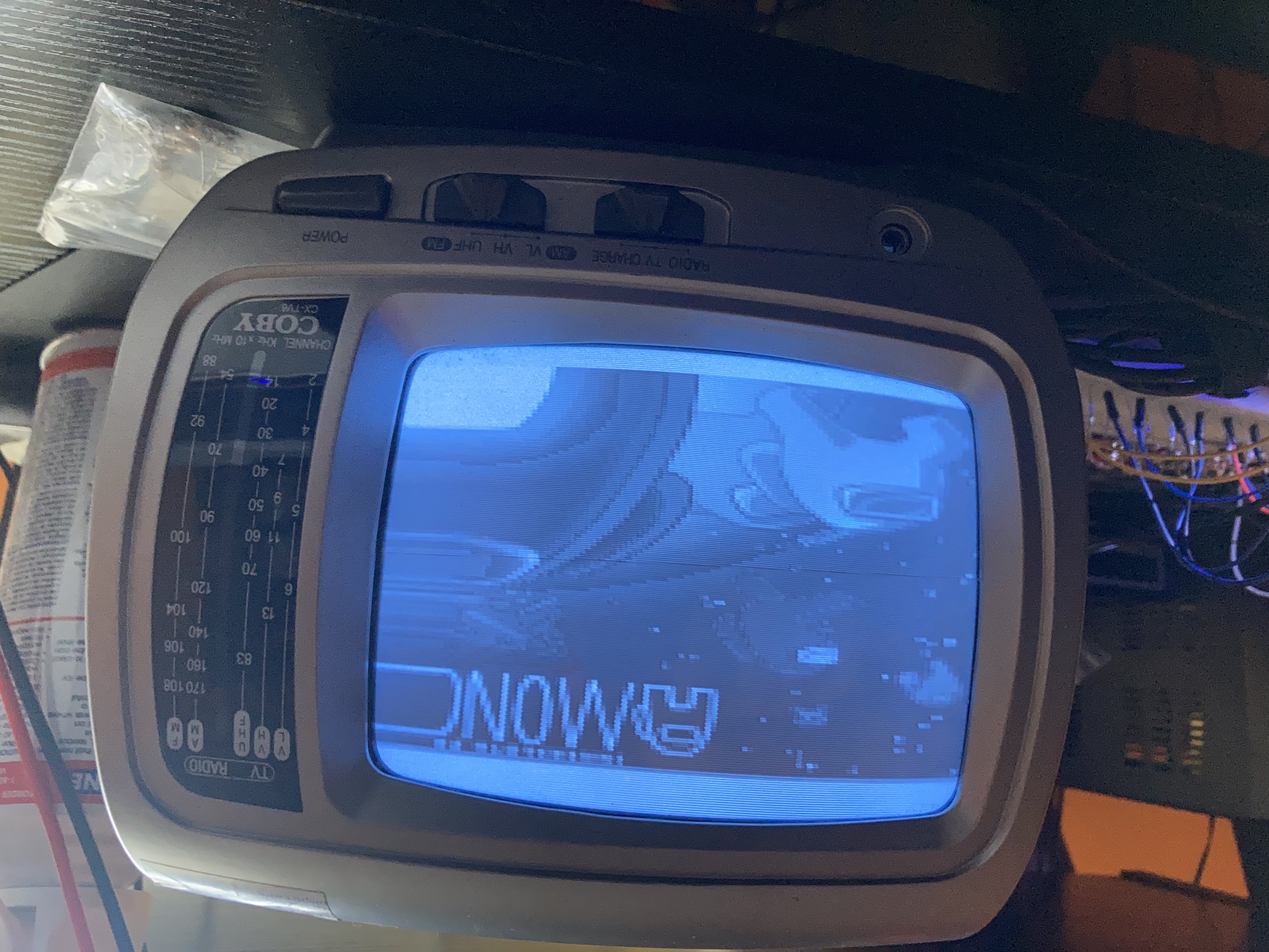
With that said, I present to you my adventures in using an Arduino Uno to make composite video. The result, so far, is this lovely image:
I will be splitting this blog post over the course of several posts, to even out pacing, and so I can publish something without waiting for the entire post to be completed. I will be detailing some of the issues I came across, and some design decisions I made along the way. Hopefully you find this post and the follow-ups useful.
Keep in mind I am myself just learning about this stuff, so I may or may not be wrong in some stuff (hopefully minimal error, let me know if you spot anything).
Motivation
What motivated me to work on this project is an old black-and-white CRT I found at a thrift store. Could you believe it was only 5$!
The television can pick up analog video from radio (RIP), FM and AM radio, and also be able to be fed composite video on the back.
That, and the challenge of getting composite working on a weak (relatively speaking) processor of an Arduino, the ATMega328P.
Composite Video
To those who don’t know what is composite video, it’s the yellow video that is part of your RCA connector from older equipment like the Wii or old DVD players. The other two RCA connectors, White and Red, are for left and right audio respectively.
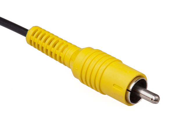
Through that one cable, it is able to take color and luminance information and display it on screen. Quite impressive actually, especially given that the color was an addition to the original black-and-white specification of composite (they had to use some high frequency and phase trickery to get it backwards compatible). I will not be diving into the color portion of composite, as it’s a little more complex with phase matching for the color signal, the Arduino already struggling with B&W, and the fact I don’t have a color CRT to test it with (yet).
There are two main video standards: NTSC and PAL. The standards determine things like the frame rate, timing of the signal, and the vertical resolution. So NTSC defines how the image is made up, and Composite defines how that image is transmitted over the wire. I will be using NTSC in this blog.
Composite video is closely related to transmission over radio waves, as both are essentially “over one wire”. That is why I think the television I have has the option to input composite: when they were designing it for radio reception, it was minimal cost to add the composite input.
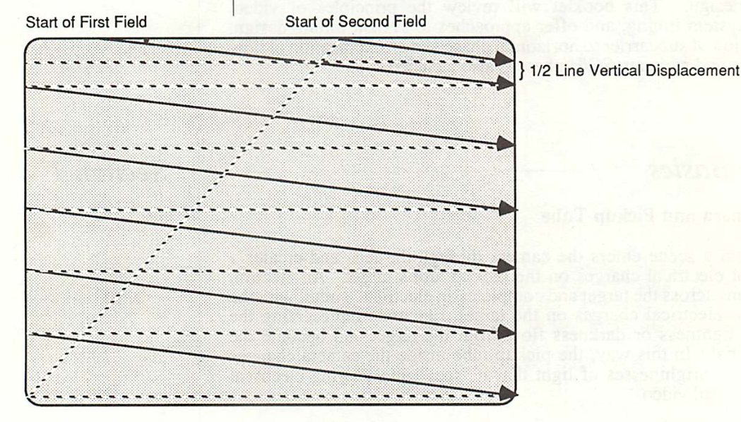
The video receive is drawn from left to right, line by line going down. With NTSC, an image is actually drawn at ~60fps, but only half of the horizonal resolution. On the next scan, the image is drawn half a line down from the previous image. This results in an interlaced video format.
Like a lot of video signals, the following make up the basic components of composite video:
- The video itself, scanned horizontally from left to right
- A horizontal back and front porch: Regions not drawn on the screen, allowing the CRT beam time to go back to the start of the line
- A vertical back and front porch: Same thing as the horizontal porches for the vertical scan
- A horizontal and vertical sync signal, to allow the CRT’s oscillator to match the receiving signal. Otherwise the video signal will move over time (ever noticed that at times with older tvs?)
I will not be going too much into detail about NTSC and the protocol, but I have linked below ([2], [3]), great resources on NTSC and the signal itself. [2] was especially helpful to me initially as it included the IRE and timing levels needed, and I did not find [3] until later.
Voltage Output and IRE
You will find a lot of resources on composite video give the voltage in IRE. An IRE, with the Wikipedia article linked in [4] and in BT.1700([3]), is a relative measure of a composite video signal. For NTSC composite, 100IRE is equivalent to 714.3mV, and -40IRE is -285.7mV. If you add them up, that makes NTSC a 1Vpp signal.
While it does say a negative voltage is needed, I’ve found that feeding a positive-only signal also works, as long as the relative levels are the same. So I used that, feeding in a 1Vpp signal.
Composite is meant to go into a 75Ω load.
Arduino and DAC
Enough explaining, let’s get started with the Arduino. Step 1 would be to have a DAC (digital to analog converter). Unfortunately the Arduino does not have an on-chip DAC, so we’ll have to get creative. We could buy a DAC module and use that, but those might be limited by the output speed. I have a better idea: let’s make one!
It’s not too difficult, trust me. A popular type of DAC that is easy to build is an R2R dac. As you can guess, it’s made up of a resistor R, and double of it (2R). The image below showcases how an R2R DAC is made.
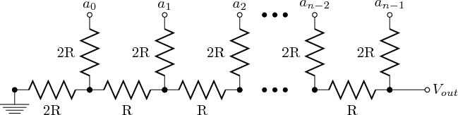
The advantage of this DAC is it’s easy to build, no heavy calculations required, and it will go as fast as the digital input changes (to a point, but sufficient for our purposes).
The output impedance of an R2R DAC is just R, which makes figuring out the R easy! We want a 1Vpp signal, and the input is a 5v signal (Arduino’s digital IO output). And we know our input impedance into composite should be 75Ω, so…
\[\begin{eqnarray} V_{out} = V_{in}*\frac{R_{load}}{R_{imp}+R_{load}} \nonumber \\ 1v = 5v*\frac{75\Omega}{R_{imp}+75\Omega} \nonumber \\ 0.2 = \frac{75\Omega}{R_{imp}+75\Omega} \nonumber \\ R_{imp}+75\Omega = \frac{75\Omega}{0.2} \nonumber \\ R_{imp}+75\Omega = 375 \nonumber \\ R_{imp} = 300 \nonumber \\ \end{eqnarray}\]So a 300Ω resistor for R in our R2R-DAC should be sufficient. I had only 330Ω laying around, leading to a maximum voltage of 0.93v. Close enough.
Yes the non-matching impedances may cause some extra reflections and other badness, but we are dealing with a low frequency (relatively) speaking signal, it’s fine.
Later on through experimentation, I found out that the TV doesn’t correctly have a 75Ω load (measured the signal with the scope), so putting a 100Ω resistor on the output of our DAC in parallel with the composite signal leads to a ~1Vpp signal going to the TV.
Pins to use
Now we have a DAC that we can feed in a digital input, but which pins to use? You might just say “use any pin and toggle them on individually”. There is a downside to that.
In microcontrollers, pins are grouped into Ports, usually 8 or 16 pins per port. The ATMega has 8 pins per port and 3 ports: PortB, PortC, and PortD. Each port is a hardware block, each with their own registers (think like a memory location) to control it. If we have our pins scattered across two ports, we must write to two separate registers, which all takes time extra. If we group all of our pins into a signal port, that means we only have to write to one register.
Regarding the number of bits to use, I wanted to go with 8 bits for the DAC, for two reasons. One, I think 8 bits is good for our video signal, and that is the maximum anyways with 8 pins per port. And second, if we have an entire port dedicated for the DAC, we can directly write to the output register the value we want. If there was anything else on that port, and we wanted to preserve the state of those other IO, then we will need to read, modify, then write the register contents, rather than just a write operation.
As for port mapping on the Uno, we don’t have much option. Only PortD is fully mapped out on an Arduino Uno (pins 0 to 7), as PortC only has 5 pins on the chip, and pins B6 and B7 are used by the 16Mhz crystal.
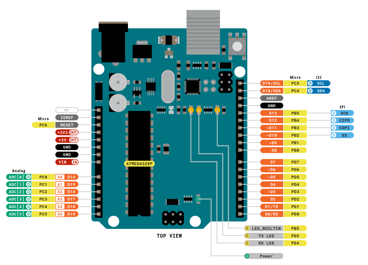
In order to use PortD completely, we must forgo the Arduino bootloader, which allows USB programming, and use an external programmer like an AVR Usbasp. I though it was worth it, and I already had the programmer with me, so that is the route I went. A small price to pay for salvation. I mapped it so pin D0 is the LSB of our DAC, and D7 is our MBS.
IRE signals to DAC
To go from an IRE level to the DAC value, we can use the following equation. Note that the IRE can go down to -40 to 100, so our range must be shifted.
\[DAC = \left\lfloor 256 * \frac{IRE+40}{140} \right\rceil\]Here are some pre-calculated output levels, as we will be hard coding these in our firmware:
- Blanking Signal: IRE=0, DAC=73
- Sync Signal: IRE=-40, DAC=0
- Black: IRE=7.5, DAC=87
- White: IRE=140, DAC=255
As the lightness range is shifted, to go from a 0-255 lightness value to DAC, we can use the following equation:
\[DAC = \left\lfloor \left( \frac{L}{255} * (255-87) \right) + 87 \right\rceil\]Next Time
That is all I have for now, next post I will be going into the Arduino firmware itself, and the rabbit that eventually led me to do some inline assembly (gasp!) and instruction timing analysis.
For now, cheers, and thanks for all the fish!
Post-Edit
Sources, References, and Good Resources
- Image of composite cable: https://en.wikipedia.org/wiki/File:Composite-video-cable.jpg
- Great resource on NTCS: https://www.technicalaudio.com/pdf/Grass_Valley/Grass_Valley_NTSC_Studio_Timing.pdf
- BT.1700. I did not found out about this until I started writing this post, and it would have saved me some time: https://www.itu.int/rec/R-REC-BT.1700-0-200502-I/en
- IRE: https://en.wikipedia.org/wiki/IRE_(unit)
- R2R DAC: https://en.wikipedia.org/wiki/Resistor_ladder#R%E2%80%932R_resistor_ladder_network_(digital_to_analog_conversion)
- R2R DAC image: https://commons.wikimedia.org/wiki/File:R2r-ladder.png
- Arduino Pinout: https://docs.arduino.cc/resources/pinouts/A000066-full-pinout.pdf