Arduino and Composite Video, part 2: Firmware
Preface: This page loads MaxJax with the following code.
<script src="https://polyfill.io/v3/polyfill.min.js?features=es6"></script>
<script id="MathJax-script" async src="https://cdn.jsdelivr.net/npm/mathjax@3/es5/tex-mml-chtml.js"></script>
EDIT 2025-05-28: I have published the code I used in this post on my Github, feel free to check it out.
Welcome back to Part 2 of my Arduino Composite video adventures!
Last time in Part 1, I went a little bit over composite video, the analog circuitry (just a DAC) and pin mapping for an Atmega328P drive. In this post, I will be going over my firmware adventures.
Something to keep in mind when reading this is I had to do a lot of debugging, troubleshooting, and research to even get to the first usable code. This blog is simply an overview of the adventure I went through, and hopefully there’s something to learn from that.
I also am partially going off memory and code backups I made, which where spurious.
Composite Signal: More Details
Typing this post, I realized I left out many details in the previous post about composite signaling that will help to understand what I am doing.
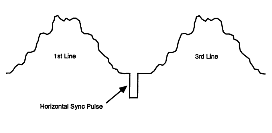
The composite signal is made up of “horizontal lines” (H), each taking ~63.5uS. An entire image scan with interlacing takes 525 lines to draw, drawing 262.5 lines per scan (we will address the 0.5 line).
When I learned about composite signaling, I looked at the entire signal as made up of horizontal lines. This thinking may not be appropriate for other implementations, as some “lines” aren’t really lines and includes things like half a line and half an equalization and sync pulse. For me though, it worked, especially when later on architecturing the firmware.
For a normal horizontal line, we start with a horizontal front-porch, sync, and back-porch signal. Note that technically we ought to treat the front-porch as part of the previous line, but treating it part of the current line also works when building up this system.
The porches and sync signals are as follows:
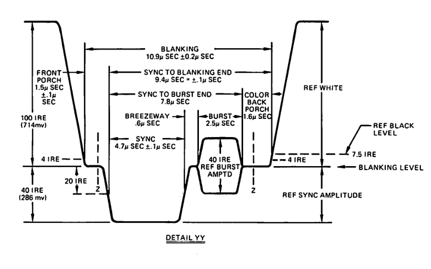
After this signal is the horizontal data, which is between black (7.5IRE) and white (100IRE) for the rest of the horizonal line.
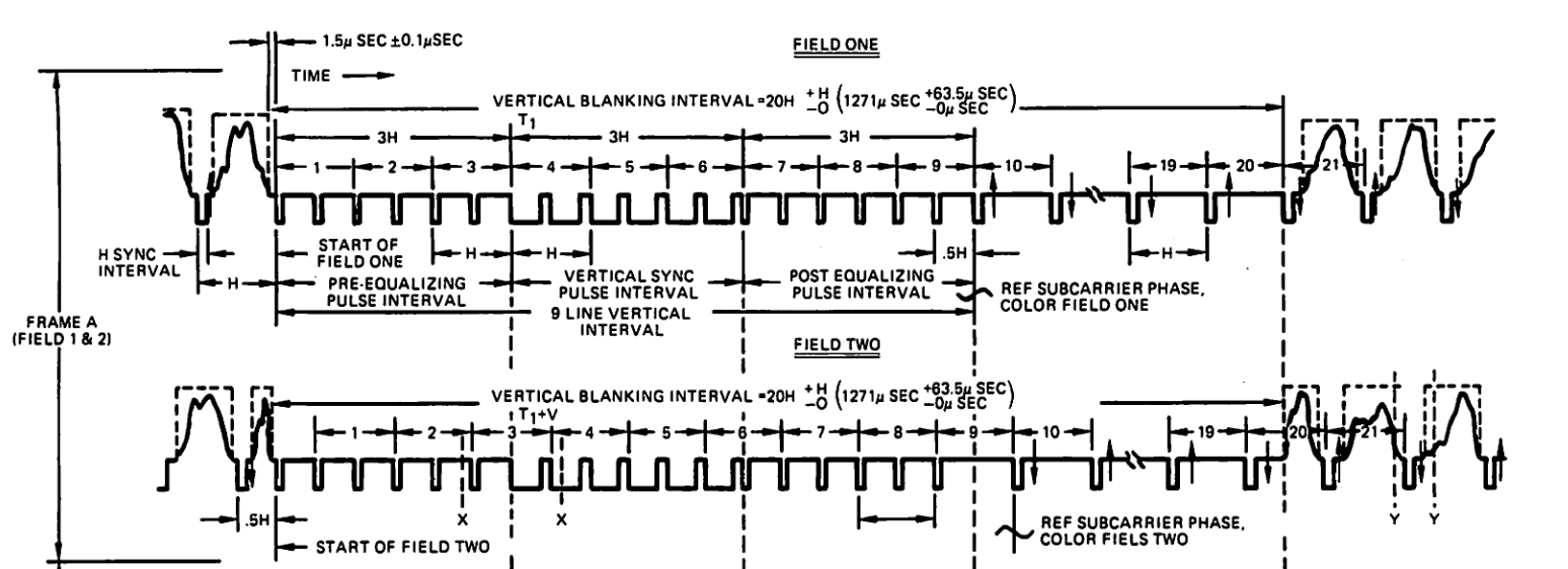
At the start of an image scan, a vertical sync and equalization pulses are sent. Six equalization pulses are sent, followed by 6 v.sync pulses, then 6 equalization pulses.
A v.sync and equalization pulse are as follows, shown back-to-back:
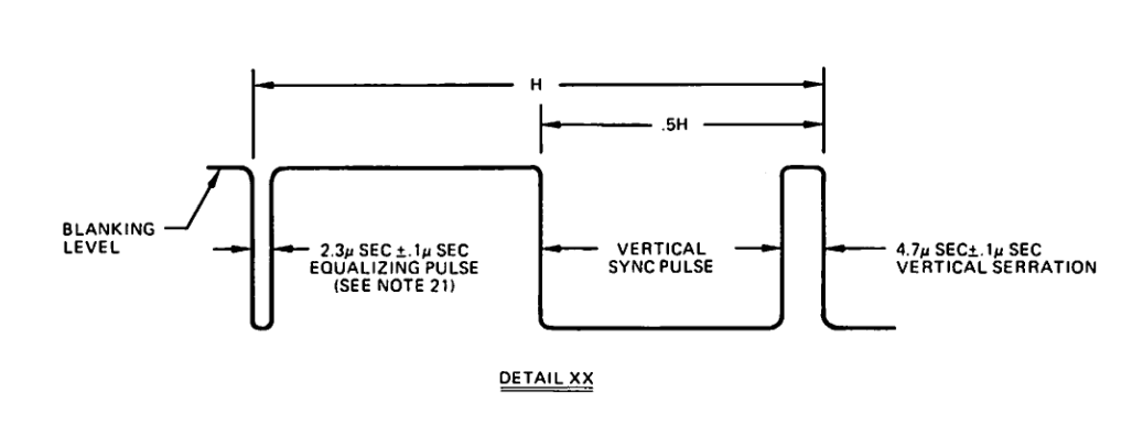
A v.sync and equalization pulse is half the duration of a horizontal line. This allows us to think of two of those signals as a single “horizontal line”.
After this, 10 blank horizontal lines are sent. They are the same as regular drawn horizontal line, but instead of a lightness the output is held at Blanking level.
When the screen reaches the 262th line, only half a normal horizontal line is sent. In the middle of the line, an equalization pulse is sent for the rest of that line. This is followed by another 5 equalization pulses, 6 sync pulses, and 5 equalization pulses. Then 10 blanking lines, and the image data again until the 525th line, in which we repeat the image scan again.
This should cover the top level detail about driving a composite signal. Feel free to look over Source #1 and #2 for extra resource, they are quite handy.
Build Setup
In order to build the code and upload it, I used a custom makefile that builds the C program (a single C file) and uploads it using AVRDUDE. The reason I didn’t use the Arduino IDE is primarily because I wanted full control over the build process, and because I prefer it over the IDE route for simple programs like this. Plus I already had it from another project I could re-use.
By default with the Arduino IDE, with void setup and void loop, the Arduino sets up some peripherals in ways that may be undesirable, such as the usage of Timer0 for the millis() and delay() functions in this case.
While I did go with the bare-C and makefile route, I also could have used the Arduino IDE by simply directly calling void main, which will skip all of Arduino’s initializations while still allowing the usage of Arduino libraries, not that I needed any for this project.
Below is the makefile I used:
PORT=/dev/ttyUSB0
MCU=atmega328p
TARGET=main

LDFLAGS=-Wl,-gc-sections -Wl,-relax -Wl,-Map=$(TARGET).map,--cref
CFLAGS=-g -Wall -mmcu=$(MCU) -O3

default: compile size

compile:
	avr-gcc $(CFLAGS) $(TARGET).c -o $(TARGET).elf
	avr-objcopy -j .text -j .data -O ihex $(TARGET).elf $(TARGET).hex

quick: compile size program

size:
	avr-size -C --mcu=$(MCU) $(TARGET).elf

program:
prog:
	avrdude -v -P usb -p $(MCU) -cusbasp -U flash:w:$(TARGET).hex

clean:
	rm -rf *.hex *.bin *.o *.elf doxygen_out/

asm:
	avr-objdump $(TARGET).elf -d > $(TARGET).d
Humble Firmware Start
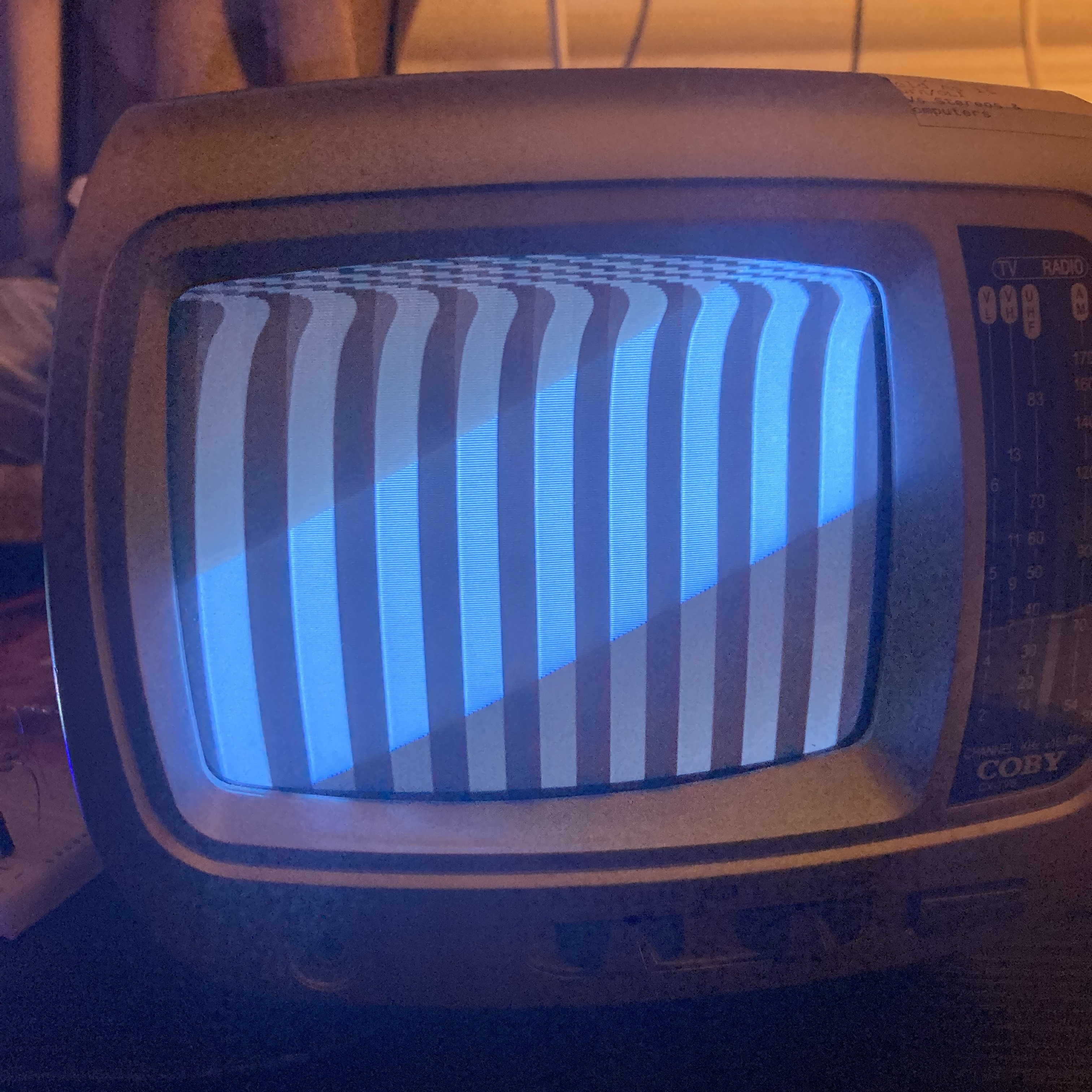
When I started with this project, my first goal was to just get vertical black and white strips displayed. This is because each horizontal scan can use exactly the same callback, so I could focus on troubleshooting and timing.
There was a lot of code and debugging that came before what I am about to show, mostly in troubleshooting and understanding composite video myself. For example, initially I did an entire 525 lines per scan before I realized I needed to interlace the video. This was just the first saved copy.
I initially opted to have an infinite loop draw the entire display over and over. The following I did:
- Send out a vertical sync, equalization pulses, and 10 blank horizontal lines
- Send 242 horizontal lines
- Send a half a horizontal line with a sync pulse (at the 263th horizontal scan)
- Send a vertical sync pulse again
- Send 242 horizontal lines again
- Rinse and repeat
If every function, for example the horizontal drawing function, took the exact time (or close) that it required, it should all align up. This isn’t ideal, and we’ll fix that later.
The main of my application looked as follows:
int main(void){
    uint16_t horizN;
    // setup PortD to be the main GPIO out
    DDRD = 0xFF;

    for(EVER){
        horizN = 242;

        verticalSync();
        while(horizN--){
            horizonalLine();
        }
        horizVideoHalf();

        horizN = 240;
        verticalSync2();
        while(horizN--){
            horizonalLine();
        }
    }

    return 0;
}
First was initiating PORTD to all be outputs, then in an infinite loop draw the screen as I described above.
Each of the functions sends out the signal and controls for it’s own delays.
Delay Functions
I used the #include <util/delay.h> function _delay_loop_1(n) for delays. The function use bare metal assembly to delay the application by 3*n clock cycles, plus 2 clock cycles for their setup. I also used _delay_loop_2(n) when needed, the only difference is using allowing a 16-bit delay value, and a higher clock cycle per n (4 vs 3), which looking back now I did not take into account at all.
To calculate a delay number, I took the time I needed to delay for, divide that by the MCU clock period (1/16E6), then divide that by 3 clock cycles. I discounted the ~2 clock cycle setup as tolerance, or when I needed to round the delay number.
For the small delays required, it is better to use those delay functions than something more complicated with timers.
Horizontal Sync and Porch
So I made a horizFontPorch function that sends out that exact desired signal:
void horizFontPorch(void){
    // delay of 1.5uS
    PORT_SET = VOLTAGE_BLANKING;
    _delay_loop_1(8);       // delay for 1.5uS, 8*3 instructions
    PORT_SET = VOLTAGE_SYNC;
    _delay_loop_1(25);       // delay for 4.7uS, 25*3 instructions
    PORT_SET = VOLTAGE_BLANKING;
    _delay_loop_1(25);       // delay for 4.7uS, 25*3 instructions
}
Horizontal Data
Each horizontal line must take 63.5uS per line. Including the horizontal sync and back porch, that means we need to draw our line in 52.6uS.
With 10 black and white stripes, I calculated the delays between switching the black and white brightness, and came up with the function as follows. The function also sends the horizontal porch and sync for convenience.
void horizonalLine(void){
    uint8_t n = 10;
    horizFontPorch();
    while(n--){
        PORT_SET = COLOR_BLACK;
        _delay_loop_1(14);
        PORT_SET = COLOR_WHITE;
        _delay_loop_1(14);
    }
}
Vertical Sync and Porch
For the vertical sync, I needed to send 6 equalization pulses, 6 sync pulses, 6 equalization pulses, then 10 empty lines. The function below handled it
void verticalSync(void){
    uint8_t n;
    n = 6;
    while(n--){
        horizFontPorch();
        _delay_loop_1(140);
    }

    n = 3*2;
    while(n--){
        PORT_SET = VOLTAGE_SYNC;
        _delay_loop_1(90);       // delay for 1.5uS, 8*3 instructions
        PORT_SET = VOLTAGE_BLANKING;
        _delay_loop_1(50);       // delay for 4.7uS, 25*3 instructions
    }

    n = 6;
    while(n--){
        horizFontPorch();
        _delay_loop_1(140);
    }

    n = 10;
    while(n--){
        horizFontPorch();
        PORT_SET = VOLTAGE_BLANKING;
        _delay_loop_1(28);
    }
}
Half Horizontal High Equalization
On the 262th scan, we need to draw half a horizontal line, then send out an equalization pulse. So I made a special function that did exactly that.
void horizVideoHalf(void){
    uint8_t n = 5;
    horizFontPorch();
    while(n--){
        PORT_SET = COLOR_BLACK;
        _delay_loop_1(14);
        PORT_SET = COLOR_WHITE;
        _delay_loop_1(14);
    }

    horizFontPorch();
    PORT_SET = VOLTAGE_BLANKING;
    _delay_loop_2(140);
}
Result
After all of that, this is the result I got:
Issue: Timing
As you might realize, there is a massive issue with how I initially architectured the firmware. If any of the drawing functions don’t draw in the correct timing, for example if the horizontal image line took too long, the entire image would be out of spec.
Another issue is during the half video scan, it is per spec required to send out 5 equalization pulses initially, not 7 (include the one the horizVideoHalf sends).
Solution: Timers
To fix the timing issue, I opted to use a timer interrupt. As we know each line is drawn every 63.5uS, I could have the timer trigger on that time and draw the current line. I kept the current line (not physical line, but a counter between 1 and 525) stored in memory, then used a state machine to determine what sort of output to draw:
int main(void){
    // setup PortD to be the main GPIO out
    DDRD = 0xFF;
    // setup Timer0 to fire an interrupt every horizontal line
    TCCR0A = 0x02;      // clear-timer on match mode
    TIMSK0 = 0x02;         // interrupt on match OutputCompareA
    OCR0A = 127;       // for a 63.5uS horizontal pulse
    TCCR0B = 0x02;         // start timer, clock/8


    currentPattern = checkmarkColor1;
    currPattIdx = 0;

    sei();          // Turn on interrupts

    for(EVER){
    }

    return 0;
}

ISR(TIMER0_COMPA_vect){
    static uint16_t horizN = 1;
    static uint16_t lineN = 0;          // actual number number

    switch(horizN){
        case 1 ... 3:
        case 7 ... 9:
        case 264:
        case 265:
        case 270:
        case 271:
            equalizationLine();
            break;
        case 266:
            equalization();
            _delay_loop_1(157);
            VSync();
            break;
        case 269:
            VSync();
            _delay_loop_1(25);
            equalization();
            lineN = 0;
            break;
        case 10 ... 20:
        case 272 ... 282:
            horizonalLineBlank();
            break;
        case 4:
        case 5:
        case 6:
        case 267:
        case 268:
            VSyncLine();
            break;
        case 263:
            horizVideoHalf();
            break;
        case 525:
            horizN = 0;
            lineN = 0;
            currentPattern = colorPattern[0];
            currPattIdx = 0;
            horizonalLine();
            break;
        default:
            lineN += 2;
            horizonalLine();
            break;
    }

    if((lineN & 0x0F) == 0){
        currentPattern = colorPattern[currPattIdx++];
        currPattIdx &= 0x01;
    }

    // if(!horizN){
        // _delay_ms(500);
    // }
    horizN++;
}
We still have the issue of a line taking too long. So what I did was remove the last delay in many of the functions above, allowing the function to always be shorter than the horizontal line duration. This way, each line trigger is consistent.
This also meant I had to reduce how much the horizonalLine is actually drawing on screen for this reason.
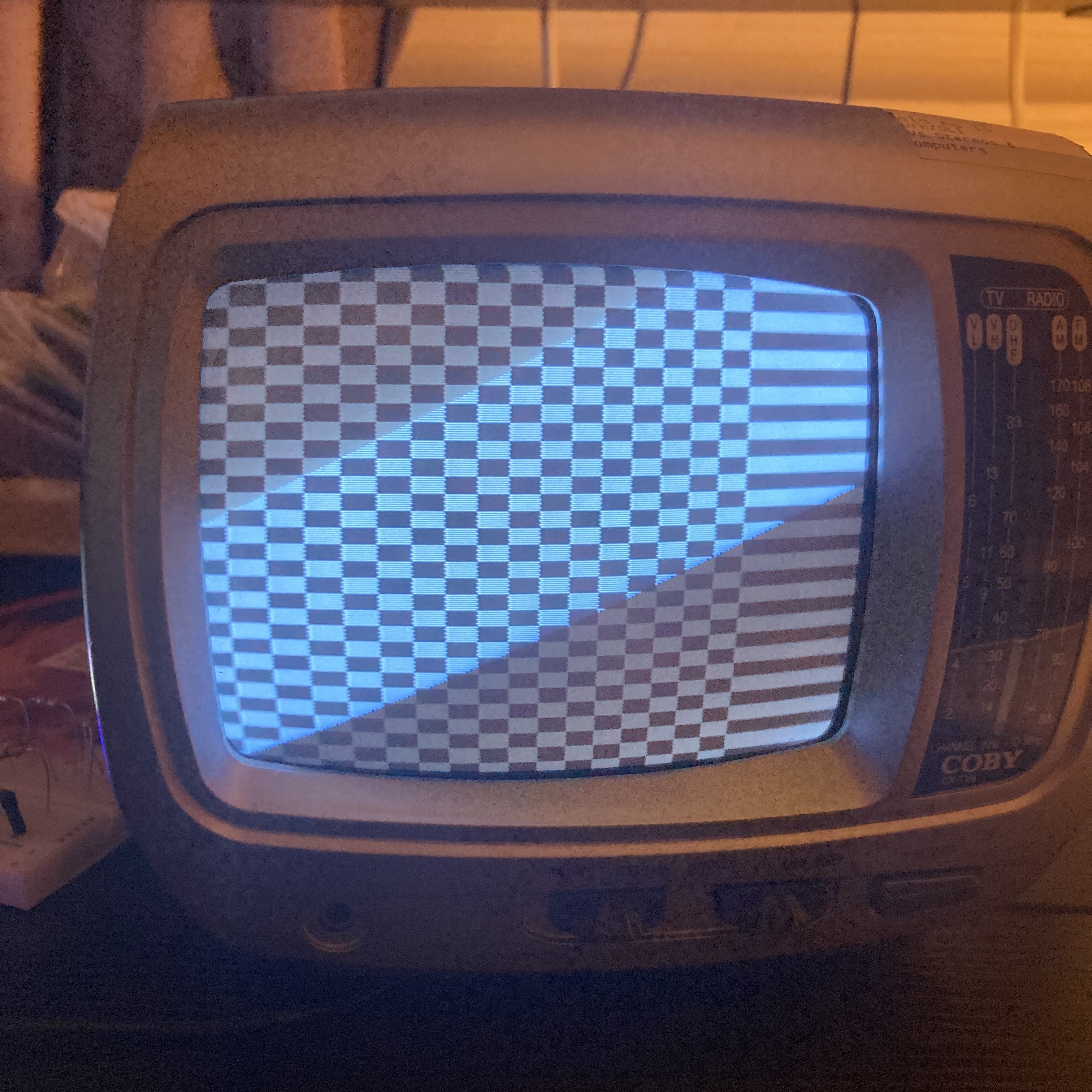
I also took this opportunity to draw a checker pattern than just vertical stripes.
After some more troubleshooting, I came to the following display
Image
Next, I decided it would be cool to draw an actual image, and what better image to draw than the iconic Among Us. For some reason I though the resolution was required was 720x480 (rather than the conventional 640x480 for a 4:3 aspect ratio), so that is why I mention that resolution in this section.
Displaying an image brought up a unique issue: Space. A 480x720 image, using one byte per pixel, we would need 345600 bytes of data. The Atmega only has 32k of flash and 8k of ram, so that is not an option. Thus I had to downside everything by 4x, resulting in a 180x120 image (I actually used 122 pixels for the vertical resolution so part of the vertical backporch has some data, although unnecessary). The image now can be stored in 21960 bytes, which is enough for Flash but not RAM memory.
Why am I mentioning RAM for constant storage?
On an AVR architecture, when you declare const uint8 VAR = x;, the compiler actually places the variable in RAM on startup. This is due to AVR’s Harvard architecture, where accessing Flash memory is different from accessing RAM, and for some C operations the compiler is designed to work around RAM stored variable, so as part of the startup routing all global variables are copied from Flash to RAM.
For what we want though, this will not work as we want all variables to be stored in Flash. The AVR solution for that is using the PROGMEM attribute, part of <avr/pgmspace.h> library. Then we use the pgm_read_byte function to read a variable stored in Flash.
Image Generation
To general the image data, I made a Python program that will open an image in greyscale mode (so no color), generate a byte array where the image data is stored back-to-back (so every 180 bytes is a new line), then dump it into a header file. Because I wanted it to be easy on the processor, I had the Python application calculate the DAC level to set to based off the image’s 0-255 lightness value. See my previous blog post for that equation.
Below is the Python application.
#!/bin/python3
from PIL import Image

file_path = 'image1.png'
out_name = '../image.h'

i = Image.open(file_path).convert(mode='L')

to_print = f"#include <stdint.h>\n#include <avr/pgmspace.h>\nconst uint8_t PROGMEM image[{122*180}] = {{"
for y in range(122):
    for x in range(180):
        # print(i.getpixel((x, y)))
        v = i.getpixel((x, y))

        v = int(((255-87) * (v / 255)) + 87)
        v = max(v, 87)
        if v < 87:
            raise UserWarning()
        to_print += f"{v},"

to_print = to_print[:-1]
to_print += "};"

with open('../image.h', 'w') as f:
    f.write(to_print)
Result, and Disappointment
I initially thought pmg_read would only take up 1 clock cycle, so I added some NOPs to control the pixel timing. Below is the new horizonalLine function, the NOP and delay commented out (I also added some global variables to keep track of where we are in the image).
void horizonalLine(void){
    uint8_t n = 65;     // <- wasn't 65 with this implementation, can't remember what it was

    horizFontPorch();
    while(n--){
        PORT_SET = pgm_read_byte_near(currImgPtr);
        // imageData = pgm_read_byte_near(image + imageXYcounter);
        // _delay_loop_1(1);      // 14
        // _NOP();
        // _NOP();
        // _NOP();
        currImgPtr++;
    }
}
Initially programming with this change, I noticed the display would not work. This was because the horizonalLine was taking too long, so I experimentally reduced the number of horizontal pixels to draw and removed all delays. I got less than 65 pixels that it can draw.
Disappointing at first, but one man’s failure is another’s adventure.
At this time I decided to do a disassembly of the main program and analyze the function. To do this, I used the avr-objdump command, which I added as the asm command in my custom makefile.
It is then I noticed something interesting, and the following change to the function actually resulted in a faster execution, bringing the number of displayable pixels up to 65 (don’t remember what it was beforehand). See if you can spot the difference:
void horizonalLine(void){
    uint8_t n = 65;
    uint16_t temp = currImgPtr;     // make a copy of the global variable so that C can optimize loop instructions

    horizFontPorch();
    while(n--){
        PORT_SET = pgm_read_byte_near(temp);
        temp++;
    }
    currImgPtr = temp;
}
Global Variable
Why am I making a copy of the global variable currImgPtr, then setting it at the end? While this seems counter-intuitive, it actually is more efficient.
The following is the dis-assembly of the previous horizonalLine function where I am directly editing the global currImgPtr variable:
Disassembly of section .text:

000056e2 <horizonalLine>:
    56e2:	99 e4       	ldi	r25, 0x49	; 73
    56e4:	9b b9       	out	0x0b, r25	; 11

000056e6 <.LBB156>:
    56e6:	88 e0       	ldi	r24, 0x08	; 8

000056e8 <.L1^B12>:
    56e8:	8a 95       	dec	r24
    56ea:	f1 f7       	brne	.-4      	; 0x56e8 <.L1^B12>

000056ec <.LBE156>:
    56ec:	1b b8       	out	0x0b, r1	; 11

000056ee <.LBB158>:
    56ee:	89 e1       	ldi	r24, 0x19	; 25
    56f0:	28 2f       	mov	r18, r24

000056f2 <.L1^B13>:
    56f2:	2a 95       	dec	r18
    56f4:	f1 f7       	brne	.-4      	; 0x56f2 <.L1^B13>

000056f6 <.LBE158>:
    56f6:	9b b9       	out	0x0b, r25	; 11

000056f8 <.L1^B14>:
    56f8:	8a 95       	dec	r24
    56fa:	f1 f7       	brne	.-4      	; 0x56f8 <.L1^B14>

000056fc <.Loc.105>:
    56fc:	21 e4       	ldi	r18, 0x41	; 65

000056fe <.L8>:
    56fe:	e0 91 02 01 	lds	r30, 0x0102	; 0x800102 <currImgPtr>
    5702:	f0 91 03 01 	lds	r31, 0x0103	; 0x800103 <currImgPtr+0x1>

00005706 <.LVL30>:
    5706:	e4 91       	lpm	r30, Z

00005708 <.LBE166>:
    5708:	eb b9       	out	0x0b, r30	; 11

0000570a <.Loc.116>:
    570a:	80 91 02 01 	lds	r24, 0x0102	; 0x800102 <currImgPtr>
    570e:	90 91 03 01 	lds	r25, 0x0103	; 0x800103 <currImgPtr+0x1>
    5712:	01 96       	adiw	r24, 0x01	; 1
    5714:	90 93 03 01 	sts	0x0103, r25	; 0x800103 <currImgPtr+0x1>
    5718:	80 93 02 01 	sts	0x0102, r24	; 0x800102 <currImgPtr>

0000571c <.Loc.118>:
    571c:	2a 95       	dec	r18
    571e:	79 f7       	brne	.-34     	; 0x56fe <.L8>

00005720 <.Loc.119>:
    5720:	08 95       	ret
It might look like a lot, but I’ll go through it instruction by instruction:
- Anything above
ldi r18, 0x41is just thehorizFontPorchfunction. The compiler thinks it’s more efficient to in-line the function rather than calling it. ldi r18, 0x41<- Loads the value of 65 into R18 (so ournvariable)lds r30, 0x0102andlds r31, 0x0103<- Load the value from the RAM variablecurrImgPtr(which is in address 0x0102) into R30 and R31 (also known as the Z register). The two instructions are to load a 16-bit word, as each instruction only loads 8-bits.- The Z register is just R30 and R31 combined to make a 16-bit word, and is used with some instructions
lpm r30, Z<- Load the value from memory address in register Z into R30out 0x0b, r30<- Output the value of R30 into PORTDlds r24, 0x0102andlds r25, 0x0103<- Load the value of the variable ofcurrImgPtrinto R24 and R25adiw r24, 0x01<- Increment R24 and R25 as a 16-bit word (treating both registers together as a word)sts 0x0103, r25andsts 0x0102, r24<- Store the variable R24-R25 back into RAMdec r18<- Decrement R18 (our pixel counter)brne .-34<- If the last operation did not result in a zero flag (so if R18 did not become zero), then go back tolds r30, 0x0102instructionret<- Returns from the current function
You might have noticed something odd. When incrementing our currImgPtr counter, it reads it from ram, increments it, then adds it back into RAM. For our purposes, this is quite wasteful. So instead making a temporary variable that is a copy, then storing the value back into RAM later, is more instruction efficient generating the below dis-assembly. See if you can spot the difference yourself!
Disassembly of section .text:

000056e2 <horizonalLine>:
    56e2:	e0 91 02 01 	lds	r30, 0x0102	; 0x800102 <currImgPtr>
    56e6:	f0 91 03 01 	lds	r31, 0x0103	; 0x800103 <currImgPtr+0x1>

000056ea <.LBB154>:
    56ea:	99 e4       	ldi	r25, 0x49	; 73
    56ec:	9b b9       	out	0x0b, r25	; 11

000056ee <.LBB156>:
    56ee:	88 e0       	ldi	r24, 0x08	; 8

000056f0 <.L1^B12>:
    56f0:	8a 95       	dec	r24
    56f2:	f1 f7       	brne	.-4      	; 0x56f0 <.L1^B12>

000056f4 <.LBE156>:
    56f4:	1b b8       	out	0x0b, r1	; 11

000056f6 <.LBB158>:
    56f6:	89 e1       	ldi	r24, 0x19	; 25
    56f8:	28 2f       	mov	r18, r24

000056fa <.L1^B13>:
    56fa:	2a 95       	dec	r18
    56fc:	f1 f7       	brne	.-4      	; 0x56fa <.L1^B13>

000056fe <.LBE158>:
    56fe:	9b b9       	out	0x0b, r25	; 11

00005700 <.L1^B14>:
    5700:	8a 95       	dec	r24
    5702:	f1 f7       	brne	.-4      	; 0x5700 <.L1^B14>

00005704 <.LBE154>:
    5704:	9f 01       	movw	r18, r30
    5706:	2f 5b       	subi	r18, 0xBF	; 191
    5708:	3f 4f       	sbci	r19, 0xFF	; 255

0000570a <.L8>:
    570a:	84 91       	lpm	r24, Z

0000570c <.LBE162>:
    570c:	8b b9       	out	0x0b, r24	; 11

0000570e <.Loc.117>:
    570e:	31 96       	adiw	r30, 0x01	; 1

00005710 <.Loc.119>:
    5710:	e2 17       	cp	r30, r18
    5712:	f3 07       	cpc	r31, r19
    5714:	d1 f7       	brne	.-12     	; 0x570a <.L8>

00005716 <.Loc.120>:
    5716:	f0 93 03 01 	sts	0x0103, r31	; 0x800103 <currImgPtr+0x1>
    571a:	e0 93 02 01 	sts	0x0102, r30	; 0x800102 <currImgPtr>

0000571e <.Loc.122>:
    571e:	08 95       	ret
More Assembly
I wasn’t satisfied with just 65 pixels alone. While reading through the dis-assembly, even for the second function, I realized some optimizations that can be done in the instruction level. Thus I attempted to make part of the horizonalLine in assembly, using the asm volatile block. I initially copied part of the C-generated dis-assembly then making it more efficient.
This is the result I came up with (the one I had a backup copy of the code for):
void horizonalLine(void){
    horizFontPorch();
    asm volatile(
        "ldi r25, 100"       "\n\t"
        "lds r30, %0"       "\n\t"
        "lds r31, %0+1"     "\n\t"
        "lpm r24, Z+"       "\n\t"
        "out 0x0b, r24"     "\n\t"
        "dec r25"           "\n\t"
        "brne .-8"           "\n\t"
        : "=m" (currImgPtr)
    );
}
Here is what it does:
ldi r25, 100<- Loads 100 into R25, used to count the number of pixels to drawlds r30, %0<- Loads the low 8-bit address of currImgPtr (%0) into R30 (Z register)lds r31, %0+1<- Loads the high 8-bit address of currImgPtr (%0) into R31 (Z register)lpm r24, Z+<- Reads from flash and loads the content into R24, while incrementing the Z pointerout 0x0b, r24<- Sets PORTD to R24dec r25<- Decrement R25, our pixel counterbrne .-8<- If the previous instruction did not raise a zero flag, which it will when R25 is equal to zero, then go back 3 instructions to thelpminstruction.
You might noticed I am also not storing currImgPtr back. This is because I realized that variable can be set before the horizonalLine function is called in the interrupt switch-case block, as it’s the same for a particular image line, which I am already keeping track of. The equation for the pointer to the image location in Flash is:
imageXYcounter = (lineN >> 2)*180;
currImgPtr = (uint16_t)image+imageXYcounter;
Where image is the image array stored in flash.
Something else you might have noticed is changing the lpm instruction to add a plus symbol (Z+). Reading through the datasheet, I realized that the lmp instruction has a variant that will automatically increment the Z register, without a clock cycle increase! This was a great improvement, and I was surprised the compiler did not optimize for this.

More improvements
I knew that horizFontPorch had delays for the sync and porch periods, so I though “what if I used those delay to execute some loading instructions?”.
And thus, meet the below assembly code. This performs much better, able to draw ~100 pixels on screen.
// draws 2 lines, as we want a checkmark
void horizonalLine(void){
    asm volatile(
        // horizonal porch, send a blank signal
        "ldi r25, %[cont1]"     "\n\t"
        "out 0x0b, r25"         "\n\t"
        // delay for 1.5uS (24 clock cycles) , let's do some math!
        // take the current line number, then divide by 4 (right shift 2)
        "lds r18, %0"       "\n\t"      // 2 clk
        "lds r19, %0+1"     "\n\t"      // 2 clk (4)
        "lsr r19"           "\n\t"      // 1 clk (5)
        "ror r18"           "\n\t"      // 1 clk (6)
        "lsr r19"           "\n\t"      // 1 clk (7)
        "ror r18"           "\n\t"      // 1 clk (8)
        // now that we shifted out line number by 2, our abs max value is 131 for a 525 lines (not possible, but the max vertical scan lines)
        // so R19 should be zero, which means we can do 8-bit math without worring about r19
        "ldi r20, 180"      "\n\t"      // 1 clk (9)
        "mul r18, r20"      "\n\t"      // 2 clk (11)
        // move the contents of r0:r1 back to r18-r19
        "movw r18, r0"      "\n\t"      // 1 clk (12)
        // now we add out image pointer to the image XY counter
        "ldi r30, %1"       "\n\t"      // 1 clk (13)
        "ldi r31, 0"     "\n\t"         // 1 clk (14)
        "add r30, r18"      "\n\t"      // 1 clk (18)
        "adc r31, r19"      "\n\t"      // 1 clk (16)
        // now currImgPtr lives in r30:r31 (Z register)
        // we have 8 instructions left, with two to load value, so 7 NOP
        "NOP\n\t" "NOP\n\t" "NOP\n\t" "NOP\n\t"
        // "NOP\n\t" "NOP\n\t" "NOP\n\t"
        // now we
        "ldi r25, %[cont2]"     "\n\t"
        "out 0x0b, r25"         "\n\t"
        // now we wait for 75 instructions, so we make a loop
        // 1 instruction for loading value, and 1 to exit, 1 after to load next port value, so 72 wait states. 3 cycles each, so 24 instructions
        "ldi r25, 24"     "\n\t"
        "dec r25"         "\n\t"
        "brne .-4"        "\n\t"
        // second blanking pulse
        "ldi r25, %[cont1]"     "\n\t"
        "out 0x0b, r25"         "\n\t"
        // same delay as above
        "ldi r25, 24"     "\n\t"
        "dec r25"         "\n\t"
        "brne .-4"        "\n\t"
        // sending the image itself
        "ldi r25, 100"       "\n\t"
        "lpm r24, Z+"       "\n\t"
        "out 0x0b, r24"     "\n\t"
        "dec r25"           "\n\t"
        "brne .-8"           "\n\t"
        : // no output
        : "m" (lineN), "m" (image), [cont1] "i" (VOLTAGE_BLANKING), [cont2] "i" (VOLTAGE_SYNC)
    );
}
Current Issues and Future
One issue still with the firmware is the horizonalLine function must end before the next interrupt is started. This means that part of right side of the image would not be drawn, and will look stretched. What I can do is to move the horizontal front porch to the end by setting the output to a Blanking level then exiting, giving me a 1.5 uS leeway at the end.
I might attempt to write this project entirely in assembly, if I feel like loosing my mind.
I might also try to make a similar application for an STM32F microcontroller. With it’s faster processor, and DMA capability, I probably can have the micro load images (or even video) from an SD card to be displayed, as the DMA can be used to handle transfers while the CPU does other stuff.
Post’s End
I am new to composite video, so I might be wrong in the way I went about some things. I am hoping though that you were able to take something away from my post, even if just lessons in optimizing code with your specific processor.
Key Takeaways, imo
- For anything remotely time-critical or time-consistent, try to use timers and interrupts.
- If you are running into timing issues or slow code in your firmware, after you have optimized the code in C, run a dis-assembly to inspect what the compiler generates. You might find some inefficient processes for your application.
- Have a quick read through your processor’s instruction set. There might be some handy instructions that might save you if you are time stringent.
Sources, References, and Good Resources
- Great resource on NTCS: https://www.technicalaudio.com/pdf/Grass_Valley/Grass_Valley_NTSC_Studio_Timing.pdf
- BT.1700. I did not found out about this until I started writing this post, and it would have saved me some time: https://www.itu.int/rec/R-REC-BT.1700-0-200502-I/en
- PROGMEM library: https://www.nongnu.org/avr-libc/user-manual/group__avr__pgmspace.html
- Atmega328P Datasheet: https://ww1.microchip.com/downloads/en/DeviceDoc/Atmel-7810-Automotive-Microcontrollers-ATmega328P_Datasheet.pdf
- AVR Instruction Set: https://ww1.microchip.com/downloads/en/DeviceDoc/AVR-Instruction-Set-Manual-DS40002198A.pdf